Quantcast
Channel: Basic Drilling Formulas – Drilling Formulas and Drilling Calculations
Viewing all 38 articles
Browse latest View live

Difference between True Vertical Depth (TVD) and Measured Depth (MD)

$
0
0

I have a question asked regarding what the differences between True Vertical Depth (TVD) and Measured Depth (MD). Today, I will describe both definitions and their importance for calculation in a drilling field.

True Vertical Depth (TVD) is measured vertically from the surface down to a certain target down hole.

Measured Depth (MD) is the total length of the wellbore measured along the actual well path.

See the following illustration for more understanding.

True Vertical Depth (TVD) is used for following calculations:

Hydrostatic Pressure Calculation

Hydrostatic Pressure (HP) Decrease When POOH

Formation Temperature Estimation

Drill pipe pulled to lose hydrostatic pressure 

Kill Weight Mud Calculation

Formation Pressure from Kick Analysis

Leak Off Test (LOT) Calculation 

Formation Integrity Test (FIT) Calculation

Equivalent Circulating Density (ECD) 

Surface Pressure During Drill Stem Test 

Measured Depth (MD) is used for following calculations:

Annular volume

Drill string and tubular volume 

Well control as stokes pump in the drill string and in the annulus, pressure schedule for wait and weight method well control.

Reference book: Drilling Formula BookFormulas and Calculations for Drilling, Production and Workover, Second Edition


How To Determine Hole Size By Fluid Caliper

$
0
0

This article will demonstrate you how to determine hole size by fluid caliper. First of all, you need to know what is the fluid caliper is. The fluid caliper is one simple way to calculate hole diameter. The concept is based on hole volume, annular capacity, and inner capacity. You pump any substance and when you seen it on surface, you back calculate the hole size based on strokes pumped. It is quite tricky to explain so I would like you to see the example below which it will make you clear about what I say.


7” casing shoe is set at 5000’MD/4500’TVD

7” casing 23 ppf, ID 6.33 inch

4” drill pipe is used to drill the well and its ID is 3.34 inch.

4-3/4” drill collar is used as BHA and its ID is 2.5 inch. The length of drill collar is 500 ft.

This hole section is used water based mud and the bit size is 6-1/8”

Drill to section TD at 10,000’MD/9,000’TVD then drop carbide once TD is reached.

Pump output is 0.1 bbl/stroke.

Surface line from pumps to rig floor is 20 bbl.

Carbide is detected by a gas sensor on surface after 4,000 strokes pump.

With the given information, determine what is the hole size of the open hole section.

The basic drilling formulas that you need to know are inner capacity and annular capacity calculation.

1st step – Determine Inner Capacity and Annular Capacity of All Parts

Inner capacity of 4”DP

Inner capacity of 4”DP = 0.01084 bbl/ft

Inner capacity of 4-3/4”DC

Inner capacity of 4-3/4”DC = 0.00607 bbl/ft

Annular capacity between 4” DP and 7” Casing

Annular capacity between 4” DP and 7” Casing = 0.02383 bbl/ft

I assign “d” is the open hole diameter.

Annular capacity between 4” DP and open hole

Annular capacity between 4 3/4” DP and open hole

2nd step – Determine Volume of All Parts

Volume in 4”DP = Inner capacity of 4”DP x length of 4” DP

Volume in 4”DP = 0.01084 x 9,500 = 103 bbl

Volume in 4-3/4”DC = Inner capacity of 4-3/4”DC x length of 4-3/4”DC

Volume in 4-3/4”DC = 0.00607 x 500 = 3 bbl

Volume between 4”DP and 7” Casing = Annular capacity between 4” DP and 7” Casing x length of 4” DP inside 7” casing

Volume between 4”DP and 7” Casing = 0.02383 x 5,000 = 119 bbl

Volume between 4”DP and open hole = Annular capacity between 4” DP and open hole x length of 4” DP inside open hole

Volume between 4-3/4”DC and open hole = Annular capacity between 4-3/4”DC and open hole x length of 4-3/4”DC inside open hole

3rd step – determine hole size. The total volume pump is equal to total volume in the system.

With the pump output of 0.1 bbl/stroke, 4000 strokes equate to 400 bbl.

In the following equation, I account for the surface volume from the pump to the rig floor.

Solve the equation to get d, d is equal to 6.97”.

Answer: You will get the hole size based on the fluid caliper of 6.97 inch.

I wish this article will give you idea on how to calculate hole size based on the fluid caliper.

Reference book: Drilling Formula BookFormulas and Calculations for Drilling, Production and Workover, Second Edition

Total Bit Revolution in When Running A Drilling Mud Motor and Rotating At Surface

$
0
0

I’ve got an email asking me about how to figure out the total bit revolution (RPM) at down hole when the mud motor is used in the drill string  and the rotating at surface is also conducted.

There are two components contributing in the total revolution of downhole drilling bit using mud motor.

1. The rotor RPM of drilling mud motor– each drilling mud motor has its specific performance data which will tell you how many revolutions per flow rate flowing through it.

For example (see the image below), it shows Rev/Gal which means the rotor will turn 0.147 turn/min per one gallon/min of drilling mud passing thought.

2. The rotary speed from top drive or rotary table.

The total drilling bit revolution downhole:

The total drilling bit revolution is equal to summation of the rotor RPM at specific flow rate and the rotary speed on surface.

Please follow the example below to determine the bit revolution down hole.

The performance data of mud motor -

Rev/Gal = 0.147

Flow rate = 320 gpm

Rotary speed = 220 rpm

The rotor rpm based on 320 gpm = 0.147 x 320 = 47 rpm

Total bit revolution down hole = 47 + 220 = 267 revolution per minute (rpm)

Ref book: Drilling Formula Book Formulas and Calculations for Drilling, Production and Workover, Second Edition


Critical Flow Rate – Drilling Hydraulics

$
0
0

Critical flow rate is the flow rate at the transition point between laminar and turbulent flow. The first step of the critical flow rate determination is to figure out the critical velocity and then substitute it into the annular flow rate.

To get the point at the transition period, the critical Reynold Number for laminar flow must be around 3470 – 1370na. With this relationship, we can determine the critical velocity by rearranging the Reynold Number and Effective Viscosity equation.

The effective viscosity equation for critical velocity is listed below:

The Reynolds number equation for critical velocity is listed below:

The critical annular velocity equation is listed below:

Where;

Vc = critical velocity in ft/sec

Rec = Reynold Number in the annulus

µea = effective viscosity in the annulus, centi-poise

na = power law constant (flow behavior index)

Ka = power law constant (consistency factor)

W = mud weight, ppg

Dh = Diameter of wellbore, inch

Do = Outside Diameter of tubular, inch

After we get the critical velocity, we can figure out the critical flow rate by the following equation.

Where;

Qc = Critical flow rate, gpm

Vc = critical velocity in ft/sec

Dh = Diameter of wellbore, inch

Do = Outside Diameter of tubular, inch

Please follow the step-by-step calculation to learn how to determine the critical flow rate.

Power law constant (flow behavior index), na = 0.51

Power law constant (consistency factor), Ka = 6.63

Mud weight = 10 ppg

Hole diameter = 12-1/4”

Drill pipe size = 5”

Determine the critical annular velocity by substituting factors into this equation.

Vc = 3.82 ft/sec

Then we can figure out the critical flow rate.

Qc = 1172 GPM

Reference:  Drilling Hydraulic Books

Equivalent Circulating Density (ECD) Using Yield Point for MW less than 13 ppg

$
0
0

Another way to determine equivalent circulating density (ECD) is to use yield point.

This formula below is used to calculate the ECD and it is good for mud weight less than or equal to 13.0 ppg.

Where:

ECD is equivalent circulating density in ppg

MW is mud weight in ppg

Hold ID is inside diameter of hole in inch

Pipe OD is outside diameter of pipe in inch

YP is mud yield point

YP can be calculated by these following equations

YP = Reading at 300 rpm – PV

PV = Reading at 600 rpm – Reading at 300 rpm

Determine the ECD with the following information

MW = 9.2 ppg

Reading at 300 = 25

Reading at 600 = 40

Hole diameter = 6.2

Pipe diameter = 4

PV = 40 – 25 = 15

YP = 25- 15 = 10

ECD = 9.7 ppg

Additional articles about Equivalent Circulating Density (ECD) are as follows:

Equivalent Circulating Density (ECD) in ppg

Equivalent Circulation Density (ECD) with complex engineering equations

Effect of Frictional Pressure on ECD while reverse circulation

Effect of Frictional Pressure on ECD while forward circulation

Ref book: Drilling Formula Book Formulas and Calculations for Drilling, Production and Workover, Second Edition

Equivalent Circulating Density (ECD) Using Yield Point for MW More than 13 ppg

$
0
0

Another equation to determine equivalent circulating density is to use yield point.

This formula below is used to calculate the ECD and it is good for mud weight more than to 13.0 ppg

Where:

ECD is equivalent circulating density in ppg.

MW is mud weight in ppg.

Hold ID is inside diameter of hole in inch.

Pipe OD is outside diameter of pipe in inch.

YP is mud yield point.

YP can be calculated by these following equations.

YP = Reading at 300 rpm – PV

PV = Reading at 600 rpm – Reading at 300 rpm

AV is annular velocity in ft/min

AV can be determined by the following equation.

AV in ft/min = (24.5 x Q) ÷ (Dh2 – Dp2)

where

Q = flow rate in gpm

Dh = inside diameter of casing or hole size in inch

Dp = outside diameter of drill pipe, drill collars, or tubing in inch

Determine the ECD with the following information

MW = 13.5 ppg

Reading at 300 = 25

Reading at 600 = 40

Hole diameter = 6.2

Pipe diameter = 4

Flow rate = 200 gpm


AV in ft/min = (24.5 x 200) ÷ (6.22 – 42) = 218.4 ft/min

PV = 40 – 25 = 15

YP = 25- 15 = 10

ECD = 14.2 ppg

If you have mud weight less than 13 ppg, please read this article “ Equivalent Circulating Density (ECD) Using Yield Point for MW less than 13 ppg 

Additional articles about Equivalent Circulating Density (ECD) are as follows:

Equivalent Circulating Density (ECD) in ppg

Equivalent Circulation Density (ECD) with complex engineering equations

Effect of Frictional Pressure on ECD while reverse circulation

Effect of Frictional Pressure on ECD while forward circulation

Ref book: Drilling Formula Book Formulas and Calculations for Drilling, Production and Workover, Second Edition

Volumetric Well Control – When It Will Be Used

$
0
0

Volumetric well control method is a special well control method which will be used when the normal circulation cannot be done. It is not a kill method but it the method to control bottom hole pressure and allow influx to migrate without causing any damage to the well.

There are several situations where you cannot circulate the well as follows:

• Pumps broken down

• Plugged drill string/bit

• Drill string above the kick

• Drill string is out of the hole completely

With the volumetric method, the volume of gas influx will allow migrating and casing pressure will increase till a certain figure then a specific amount of mud will bleed off to compensate the increase in casing pressure. The volumetric method will allow the kick to surface while the bottom hole pressure is almost constant. Successful use of volumetric method requires personnel understand three basic concepts –

1. Boyle’s Law – Boyle’s law states that at constant temperature, the absolute pressure and the volume of a gas are inversely proportional in case of constant temperature within a closed system. The illustration below demonstrates volume and pressure as per Boyle’s Law.

145 volumetric method

In term of mathematical relationship, Boyle’s Law can be stated as

P1 x V1 = P2 x V1

Where;

P1 = pressure of gas at the first condition

V1 = volume of gas at the first condition

P2 = pressure of gas at the second condition

V2 = volume of gas at the second condition

2. Hydrostatic pressure – Hydrostatic pressure is pressure created by column of fluid. Two factors affecting hydrostatic pressure are height of fluid and density of fluid.

Pressure at the bottom hole equals to hydrostatic pressure plus surface pressure

Pressure (bottom hole) = Hydrostatic Pressure + Surface Pressure

We will apply this concept to see how the gas bubble will increase the bottom hole pressure.

If the gas bubble is not allowed to expanded, the gas bubble in the well migrates up will act on the mud column below and increase bottom hole pressure. Increasing in the bottom hole pressure equates to hydrostatic pressure below the bubble.

Bottom hole pressure = Gas bubble pressure + Hydrostatic pressure below the bubble

 145 volumetric method2

If we don’t want increase in bottom hole pressure, mud need to be bled off the well while the gas migrating up and the casing pressure must increase to compensate loss of hydrostatic pressure from bleed off.

In the volumetric control, there are two ways to control bottom hole pressure while allowing the gas migrating up to surface.

1. Wait and let gas migrate. The migration of gas will increase bottom hole pressure and casing pressure.

2. Bleed off mud from the annulus. Mud that is bled off must be equal to the increase in bottom hole pressure.

Both steps above must be carefully performed perform in a sequence. We will go to the detailed procedures in later post.

3. Relationship of height and fluid volume as determined by annular capacity – In order to determine volume of mud that equates to required hydrostatic pressure, we need to understand annulus capacity. It tells us how many bbl per foot in annulus and it can be calculated by this following formulas:

Annular Capacity Factor (ACF) = (OD2-ID2) ÷ 1029.4

Where;

ACF = Annular Capacity Factor in bbl/ft

OD = Outside Diameter of Annular in inch

ID = Inside Diameter of Annular in inch

Once the ACF is know, we can determine Mud Increment (MI) which is the volume of mud bled off from the annulus to reduce the annular hydrostatic pressure by the amount of the pressure required.

Mud Increment (MI) can be calculated by this following equation:

Mud Increment (MI) = (PI x ACF) ÷ (0.052 x MW)

Where;

PI = Pressure Increment in psi

ACF = Annular Capacity Factor in bbl/ft

MW = Mud Weight in the well in ppg


Well control quiz ebooks here =>well control http://amzn.to/WjtEvd

How to Select a Scientific Calculator for Oilfield Personnel

$
0
0

Working in the oilfield, you need a scientific calculator to help you solve problems with complex formulas. As you learn from this website, drillingformulas.com, you really need a scientific calculator to help you.

How-to-Select-a-Scientific-Calculator-for-Oilfield-Personnel

There are different brand companies that design scientific calculators. However, the difference in brand names might not alter the similarity in functions and programming. When you are choosing a small scientific calculator, there are a number of factors that you should consider. These factors include; functionality and efficiency, portability and durability.

Functionality and Efficiency

The main reason why we buy a calculator is for faster computations. You should choose a calculator whose programming allows you to compute all the problems in your relevant discipline. Most of the calculators can help you in calculating normal mathematic problems, logarithms, fractions, statistics, probability, etc. If the calculator that you choose can handle the mathematics problems in your discipline, then it is a good calculator.

If you are in work sites as drilling rigs, you might not need a calculator with many technical buttons. You might just need a simple scientific calculator that will handle basic mathematic problems. There is no need of buying a very expensive calculator while you will not be using most of the functions indicated on the calculator. Instead, you can save on the purchase cost by buying a simple scientific calculator with the sine, cosine and tangent buttons among other important functions and you will still enjoy the functions of a scientific calculator.

This is the calculator (Casio Advanced Scientific Calculator with 2-Line Natural Textbook Display (FX-115ES)) that I used on the rig.

Casio Advanced Scientific Calculator FX-115ES


This calculator costs you less than 20 dollars but it will work all the hard work for you.

If you are working in the discipline that will use advanced mathematics, you really need to look into the advanced one. There is a specific scientific calculator that is programmed and designed for all math problems. The mathematics calculator is ideal for college students and engineers. It gives accurate answers with simpler decimals which enable to give more comprehensive answers. Some engineering calculators also show graphical representations. These are complex calculators that some people might not need for basic mathematics. These types of calculators are good for directional drillers, engineers (drilling, production, reservoir), geologists, etc.

The programming of the calculator determines the functions that the calculator can handle.

Texas Instruments TI-83 Plus Programmable Graphing Calculator is one of the most famous advanced scientific calculators.

Texas Instruments TI-83

Portability

Personnel especially ones working on the rig need simple scientific calculators that they can carry around easily. It is therefore important to choose a calculator that can fit in your bag or pocket. It makes it easier to hold when using and also easier to use since it has small and soft buttons. However, if you work in the office working of the complex engineering project, the advanced calculator may be suit for you.

Durability

Durability is very crucial when choosing your calculator. You need to look for a calculator that comes with a dust cover, water resistant screen and joints and buttons that are not easily unmarked after continuous use. You should choose a calculator with a clear screen too. You can ask from the store if you can use the calculator in the sun. Some screens show blurred figures when they are used outdoors.

Price should never be a determinant of the quality of calculator you want to buy. If you are guided by price you will either get a counterfeit calculator or one whose keys will fade within a couple of months making it very hard for you to use some functions on the calculator.

Find the scientific calculators at cheap price from Amazon.com.

Scientific calculators

Scientific Calculators


Advanced graphing scientific calculators

Graphing Scientific Calculators


Drill Collar Weight Calculation To Prevent Drill Pipe Buckling

$
0
0

Drill collar provides weight to the bit for drilling and keep the drill string from buckling. Additionally, drill pipe should not run in compression because it can get seriously damaged therefore we need to know weight of drill collar that is enough to provide weight to the bit.


Drill-Collar-Weight-Calculation-1

Drill pipe buckle due to insufficient of drill collar

Drill-Collar-Weight-Calculation-2

Drill pipe straight because of sufficient drill collar weight

Drill collar weight in a vertical well

Drill-Collar-Weight-Calculation-3

The following formula is used to determine required drill collar weight to obtain a desired weight on bit for a vertical well.

WDC = (WOB x SF) ÷ BF

Where

WDC is drill collar weight in air, lb.

WOB is a required weight on bit, lb.

SF is a safety factor.

BF is mud buoyancy factor.

Drill collar weight in a deviated well

In a deviated well, the drill collar weight will not directly transfer to the bit because of well inclination which has direct affect on weight on bit.

Drill-Collar-Weight-Calculation-4

The following formula is used to determine required drill collar weight to obtain a desired weight on bit for a deviated well.

WDC = (WOB x SF) ÷ (BF x COS (θ))

Where

WDC is drill collar weight in air, lb.

WOB is a required weight on bit, lb.

SF is a safety factor.

BF is mud buoyancy factor.

θ  is inclination of the well.

Example: The deviated well has inclination of 30 degree in tangent section and planned mud weight is 12.0 ppg. Safety factor for this case is 25%.

What is the drill collar weight to obtain the desired WOB of 50 Klb?

Buoyancy Factor = (65.5 – 12.0) ÷ 65.5 = 0.817

SF @ 25 % = 1.25

WDC = (50,000 x 1.25) ÷ (0.817 x COS (30))

WDC = 88,333 Klb

In this case, drill collar weight in the air should be 88.3 Klb. In reality, the BHA does not only have the drill collar so you need to adapt this figure. For instant, the BHA consists of mud motor, stabilizer, LWD and HWDP which have a total weight of 30 Klb. Therefore, the actual drill collar weight is just only 58.3 Klb (88.3 – 30).

 Ref Book: Drilling Formula BookFormulas and Calculations for Drilling, Production and Workover, Second Edition

Margin of Overpull in Drillstring

$
0
0

Margin of overpull is additional tension to be applied when pulling the stuck drill string without breaking the tensile limit of the drill string. This is the difference between maximum allowable tensile load of drill string and hook load.

margin-of-Overpull-in-Drillstring

The formula for margin of overpull is described below;

Margin of Overpull = Ta – Th

Where;

Ta is the maximum allowable tensile strength, lb.

Th is the hook load (excluding top drive weight), lb.

The ratio between Ta and Th is safety factor (SF).

SF =Ta ÷ Th

Example: The drill string consists of the following equipment:

5” DP S-135, 4-1/2” IF connection, adjusted weight of 23.5 ppf = 8,000 ft

5” HWDP S-135, 4-1/2” IF connection, adjusted weight of 58 ppf = 900 ft

Mud motor and MWD, weight 20 Klb, = 100 ft

Expected hook load at TD = 270 Klb

Tensile strength of 5” DP S-135 (premium class) = 436 Klb

Tensile strength of 5” HWDP S-135 (premium class) = 1,100 Klb

90% of tensile strength is allowed to pull without permission from town.

Determine the margin of overpull from the information above.

Maximum tension will happen at the surface so 5”DP will get the most tension when pulling and since only 90% of tensile strength is allowed. The allowable tensile (Ta) is as follows;

Ta = 0.9 x 436 = 392 Klb

Th = 270 Klb at TD

Margin of over pull = 392 – 270 = 122 Klb

Safety Factor = 392 ÷ 270 = 1.45

 Ref Book: Drilling Formula BookFormulas and Calculations for Drilling, Production and Workover, Second Edition

Understand Pressure Loss (Frictional Pressure) in Drilling System

$
0
0

Frictional pressure is pressure loss acting in the opposite direction of fluid flow and today we will look into each component in pressure therefore you will get clearer picture about the frictional pressure in drilling system.

Let take a look at the simple diagram below.

Understand Frictional Pressure in Drilling 1

A mud pump creates power to move drilling fluid from point A to C and the frictional pressure or pressure loss is the amount of pressure required to transfer fluid.

Pump pressure is 2,000 psi at the starting point (“A”) and at the end point (“C”), pressure is 0 psi. This tells you that you need 2,000 psi to overcome the frictional pressure in order to move the fluid from point “A” to point “C”.

“Differential pressure between two points in the system is pressure loss while fluid is moved from one to another point.”

What is the pressure loss from “A” and “B”?

At point “B”, the pressure remaining is 1,000 psi, therefore pressure loss between “A” and “B” equals to 900 psi (2,000 – 1,100).

What is the pressure loss from “B” and “C”?

At point “C”, at an atmospheric condition, the pressure is 0 psi, therefore pressure loss between “B” and “C” equals to 1,100 psi (1,100 – 0).

Apply This Concept Into Drilling

Then we will apply this concept to understand about pressure loss in the drilling system. The simple drawing below demonstrates a simple circulating route of drilling fluid while drilling.

Understand Frictional Pressure in Drilling 2


Analysis of Pressure Loss in The Drilling System

We need to analyze each section to understand each pressure loss component.

Understand Frictional Pressure in Drilling 3

 Surface -> ∆ PSI Surface Equipment

Inside drill string, drill collar, BHA -> ∆ PSI Drill Pipe + ∆ PSI Drill Collar and BHA

Bit -> ∆ PSI Drill Bit

Annulus -> ∆ PSI Annulus DC and BHA / OH + ∆ PSI Annulus DP/OH + ∆ PSI Annulus DP/CSG

Where;

∆ PSI Surface Equipment = Pressure loss in surface equipment

∆ PSI Drill Pipe = Pressure loss in drill pipe

∆ PSI Drill Collar and BHA = Pressure loss in drillcollar and BHA

∆ PSI Drill Bit = Pressure loss across the bit

∆ PSI Annulus DC and BHA / OH = Pressure loss in the annulus between DC/BHA and open hole

∆ PSI Annulus DP/OH = Pressure loss in the annulus between drill pipe and open hole

∆ PSI Annulus DP/CSG = Pressure loss in the annulus between drill pipe and casing

In order to pump drilling fluid from the mud pit and back to surface, pump pressure equals to summation of pressure loss of all equipment which can be described in the following relationship.

Pump pressure = ∆ PSI Surface Equipment + ∆ PSI Drill Pipe + ∆ PSI Drill Collar and BHA + ∆ PSI Drill Bit ∆ PSI Annulus DC and BHA / OH + ∆ PSI Annulus DP/OH + ∆ PSI Annulus DP/CSG

Example: Well depth is 12,000’MD/10,000 TVD and planned pump rate is 400 GPM. Based on drilling hydraulics calculation, the pressure loss component s are listed below;

∆ PSI Surface Equipment =50 psi

∆ PSI Drill Pipe = 500 psi

∆ PSI Drill Collar and BHA = 30 psi

∆ PSI Drill Bit = 1500 psi

∆ PSI Annulus DC and BHA / OH = 200 psi

∆ PSI Annulus DP/OH = 600 psi

∆ PSI Annulus DP/CSG = 450 psi

What is the pump pressure required to circulate at drilling rate?

Pump pressure = total pressure loss of all equipment together.

Pump pressure = 50 + 500 + 30 + 1500 + 200 + 600 + 450 = 3,300 psi.

I wish this explanation and exercise would help you get more understanding about pressure loss.

 Note: Additional drilling formulas for hydraulic calculations that you might need to know.

Reference:  Drilling Hydraulic Books

Buoyancy Factor Table Free Download

$
0
0

Buoyancy factor is the factor that is used to compensate loss of weight due to immersion in drilling fluid and you can find the calculation from here http://www.drillingformulas.com/buoyancy-factor-calculation/.

bf-table-facbook

We have created a simple table to help people determine the buoyancy factor quickly. Let’s take a look at the table. In Figure 1, it shows the main page and you can select the mud weight range from 4.0 ppg to 19.0 ppg.

 Figure 1- Main Page BF Table

Figure 1- Main Page BF Table

For instant, we choose 8.0 ppg and the table will show buoyancy from 8.0 – 8.9 ppg (Figure 2)

Figure 2 - Buoyancy Factor for 8 ppg Range

Figure 2 – Buoyancy Factor for 8 ppg Range

 The table shows the buoyancy factor from mud weight range from 8.0 – 8.9 ppg. Additionally, the table demonstrates mud weight in kg/l. For example, if we select 8.5 ppg, the table will tell you the buoyancy factor of 0.8702 (Figure 3).

 Figure 3 - 8.5 ppg and Buoyancy Factor

Figure 3 - 8.5 ppg and Buoyancy Factor


If you want to go back to the main page, you just simply click “Go Back To Main Page”.

 Figure 4- Go Back to Main Page BF Table

Figure 4 - Go Back to Main Page BF Table

 Download the Buoyancy Factor Table from this link => Excel-icon-40-40  http://goo.gl/AIzMeS

If you think this is good for your friends, please feel free to share with them.


Buoyancy Factor with Two Different Fluid Weights in The Well

$
0
0

Buoyancy Factor is the factor that is used to compensate loss of weight due to immersion in drilling fluid and you can find more information from this article > buoyancy factor calculation .  In that article, it demonstrates the buoyancy formula only for one fluid in the wellbore. However, this time, we will have the details about buoyancy factor when inside and outside fluid are different.

Buoyancy-Factor-with-Two-Different-Fluid-Weights

Buoyancy factor with different fluid inside and outside of tubular is listed below;

equation 1

Where;

Ao is an external area of the component.

Ai is an internal area of the component.

ρo is fluid density in the annulus at the component depth in the wellbore.

ρi is fluid density in the component depth in the wellbore.

ρs is steel weight density. Steel density is 65.4 ppg.

If you can the same mud weight inside and outside, the equation 1 will be like this

equation 2

This is the same relationship as this article buoyancy factor calculation.

Let’s take a look at the following example to get more understanding.

Example

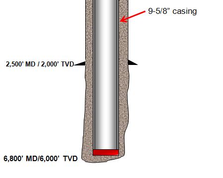
13-3/8” casing shoe was at 2,500’MD/2,000’TVD

9-5/8” casing was run to 6,800’MD/6,000 TVD.

9-5/8” casing weight is 40 ppf and casing ID is 8.835 inch.

Current mud weight is 9.5 ppg oil based mud.

The well bore diagram is show below (Figure 1).

 Figure 1 - Wellbore Diagram

Figure 1 - Wellbore Diagram

The well is planned to cement from shoe to surface and the planned cement weight is 14.0 ppg. The displacement fluid is drilling mud currently used.

Please determine the following items.

  • Air weight of casing string
  • Buoyed weight of casing in drilling mud
  • Buoyed weight of casing when cement is inside casing and drilling mud is outside casing
  • Buoyed weight of casing when cement is outside casing and drilling mud is inside casing

Air weight of casing string

Air weight of casing string, lb = length of casing, ft x casing weight, lb/ft

Air weight of casing string, lb = 6,800x 40 = 272,000 lb

Buoyed weight of casing in drilling mud

 Figure 2 - Bouyed Weight When Submersed In Drilling Mud

Figure 2 - Buoyed Weight When Submersed In Drilling Mud

Buoyed weight = Buoyancy Factor (BF) X Air Weight of Casing

equation 2.5

Buoyancy Factor (BF) = 0.855

Buoyed weight = 0.855 X 272,000 = 232,489 lb

Buoyed weight of casing when cement is inside casing and drilling mud is outside casing

 Figure 3 - Buoyed weight of casing when cement is inside casing and drilling mud is outside casing

Figure 3 - Buoyed weight of casing when cement is inside casing and drilling mud is outside casing

 We will apply the Equation-1 for this case.

Ao is an external area of the component.

Ao = π x (Outside Diameter of casing)2 ÷ 4

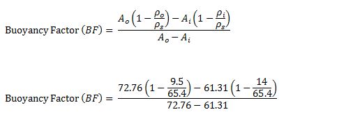
Ao = π x (9.625)2 ÷ 4 = 72.76 square inch

Ai is an internal area of the component.

Ai = π x (Inside Diameter of casing)2 ÷ 4

Ai = π x (8.835)2 ÷ 4 = 61.31 square inch

ρo = 9.5 ppf (mud in the annulus)

ρi = 14.0 ppg (cement inside casing)

ρs = 65.4 ppg.

equation 3

Buoyancy Factor (BF) = 1.22

Buoyed weight = 1.22 X 272,000 = 331,840 lb


Buoyed weight of casing when cement is outside casing and drilling mud is inside casing

 Figure 4 - Buoyed weight of casing when cement is outside casing and drilling mud is inside casing

Figure 4 - Buoyed weight of casing when cement is outside casing and drilling mud is inside casing

We will apply Equation-1 for this case as well.

All the calculation parameters are the same.

Ao = π x (9.625)2 ÷ 4 = 72.76 square inch

Ai = π x (8.835)2 ÷ 4 = 61.31 square inch

ρo = 9.5 ppf (mud in the annulus)

ρi = 14.0 ppg (cement inside casing)

ρs = 65.4 ppg.

equation 4

Buoyancy Factor (BF) = 0.42

Buoyed weight = 0.42 X 272,000 = 114,240 lb

Conclusion: At different stage of the well, you may have different buoyed weight depending on density of fluid inside and outside of the component and it is not always that buoyed weight is less than air weight.

Reference book => formulas-and-calculationFormulas and Calculations for Drilling Operations 

Volume of Cutting Generated While Drilling

$
0
0

While drilling, cuttings are generated every footage drilled and this topic will demonstrate how to determine volume of cutting entering into the wellbore.

Figure 1 - Cutting Generated While Drilling

Figure 1 - Cutting Generated While Drilling

 The following formula is used to calculate cutting volume generated while drilling;

vc - bbl per hour

Where;

Vc is volume of cutting in bbl/hr.

Ø is formation porosity (%).

D is wellbore diameter in inch.

ROP is rate of penetration in feet per hour.

Vc can be presented in several unit as follows;

Vc in gallon per hour is shown below;

vc - gallon per hour

Vc in gallon per minute is shown below;

vc - gallon per minute

Example: Determine volume of cutting in gallon per hour entering into the well bases on the following information.

Well depth 9,500’ MD/8,000’ TVD.

Average ROP = 80 fph

Average formation porosity = 20 %

Bit size = 8-1/2”

Assume gauge hole

Figure 2 - Well and Drilling Information

Figure 2 - Well and Drilling Information


Vc in gallon per hour is shown below;

vc - gallon per hour (example)

Vc = 188.8 gallon/hr

This figure tells you that with the drilling parameter, you must be able to remove the cutting faster than what you generate in order to eliminate operation issues as stuck pipe.

Reference book => formulas-and-calculationFormulas and Calculations for Drilling Operations 

Coring Cost Per Footage Drilled

$
0
0

Coring is a special process to recover wellbore rock in the well.

Figure 1 - Core from the well. Credit – Wikipedia
Figure 1 - Core from the well. Credit – Wikipedia

This article will demonstrate how to calculate coring cost per footage recovered.

coring-cost-per-foogate-drilled

 Coring cost per footage recovered is expressed below;

coring cost per foot formula

Where;

Cc = coring cost per foot

Cb = cost of core bit

Cs = cost of coring service from a service company

Cr = rig day rate

tt = trip time, hour

tc = core recovering time, hour

trc = core barrel handling time, hour

L = length of core recovered, ft

Rc = percentage of core recover, %

Example – Geologist plans to do coring from 14,000 – 14,500 ft. The information for this operation is listed below;

Coring bit = 20,000 $

Coring service price = 120,000 $

Rig day rate = 100,000 $

Expected trip in and out time = 24hours

Core recovery time = 12 hours

Core and tool handling time = 4 hours

Expected core recovery = 90 %

Determine the expected coring cost per foot.

 Figure 2 - Coring Depth

Figure 2 – Coring Depth

Solution

Cb = 20,000 $

Cs = 120,000 $

Cr = 100,000 $/day ( 4166.67 $/hr)

tt = 24 hrs

tc = 12 hrs

trc = 4 hrs

L = 500 (14,500 – 14,000)

Rc = 90 %

coring cost per foot formula-2

Cc =681.5 $/ft

Coring cost per footage drilled is 681.5 dollars.

Reference book => formulas-and-calculationFormulas and Calculations for Drilling Operations 


Solid Density From Retort Analysis Mud Calculation

$
0
0

Retort analysis is the method to determine solid and liquid components in the drilling fluid. In this article, we will adapt mass balance and retort analysis data to determine solid density in the mud.

solid-Density-In-Mud-Calculation

Mass balance for mud is listed below;

equation 1

We can rearrange the Euqation#1 in order to determine the solid density


equation 2

In the report analysis, the volume is presented in percentage and summation of solid and liquid fraction equals to one.

The unit of each parameter is described below;

Vm = mud volume, %

ρm = mud density, ppg

Vw = water volume, %

ρw = water density, ppg

Vo = oil volume, %

ρo = oil density, ppg

Vs = solid volume, %

ρs = solid density, ppg

Note: this is not only cutting weight but it includes all weights of solid (cutting and weighting material).

Example: Mud weight used for the report is 12.0 ppg and the result from the analysis showing in the following percentage;

Base oil = 60%

Solid = 35 %

Water = 5%

Base oil weight = 7.0 ppg

Water weight = 8.6 ppg

equation 3

ρs = 21.06 ppg

Total density of solid in the drilling mud is 21.06 ppg.

Reference book => formulas-and-calculationFormulas and Calculations for Drilling Operations 

How Does 1029.4 Come From?

$
0
0

1029.4 is used in several calculations in the oilfield and we’ve been asked about what is 1029.4, how it comes from, why it needs to be this figure so in this article, we will show you how 1029.4 comes from.

how-does-1029.4-come-from

First of all, we would like to give someone about the background of this figure. The 1029.4 is widely used for capacity calculations. The following equations utilizing 1029.4 are listed below;

Annular capacity, bbl/ft = (OD2 – ID2) ÷ 1029.4

Internal capacity, bbl/ft = ID2 ÷ 1029.4

Where;

ID, OD are in inch.

Annular capacity and internal capacity are in bbl/ft.

As you can see, 1029.4 is the unit conversion used to convert square inch into bbl/ft.

Let’s see how we can find this figure mathematically.

Area of circle (square inch) = (π÷4) x D2

D is diameter in inch.

For oilfield unit, the diameter (D) is inch.

In term of mathematic, Area (square inch) is equal to Volume per Height, cubic inch (in3) per inch (in).

Cubic inch per inch is not typically used in oilfield and oilfield unit usually uses bbl for volume and ft for length. Therefore, we need to convert from in3/in to bbl/ft.

The following figures are unit conversions used for the calculation.

1 bbl = 9702 cubic inch (in3)

1 inch = 0.08333 ft

Based on the unit conversions and Area of circle formula, we can put everything together like this.

1029.4 comes from-1

This is the final formula.

1029.4 comes from-2

You can see that 1029.4 is the final conversion unit for this formula.

Ref Book -> Applied Drilling Engineering Book special offer 


Driller’s Method or Wait and Weight Method – What is The Practical Well Control Method for You?

$
0
0

Driller’s method and wait and weight method (engineer’s method) are widely used to circulate wellbore influx while maintaining bottom hole pressure constant. There are a lot of opinions regarding which method is the best for well control operation therefore this article will discuss about pros and cons of both methods.

driller-or-wait-and-weight-method

Driller’s Method

The driller’s method requires two circulations to kill the well. The first circulation is to circulate influx out of the well with original mud weight. The second circulation is to kill the well with kill weight fluid. During the first circulation, the bottom hole pressure remains constant due to maintain drill pipe pressure constant while circulating. For the second circulation, in order to maintain constant bottom hole pressure, casing pressure is held constant while circulating kill mud to the bit. Once the kill mud passes the bit, the drill pipe pressure will be held constant until the kill weight mud is on surface and there is no sign of influx in the annulus.

Wait and Weight Method

The Wait and Weight method requires only one circulation. The influx will be circulated out while the kill weight mud is displaced into the well simultaneously. While pumping the kill fluid from surface to the bit, drill pipe pressure schedule must be strictly followed. After that the drill pipe pressure is maintained constant until the kill mud returns back to surface.  Some people call the Wait and Weight method as “Engineer’s Method” because there are more calculations compared to the Driller’s method.

Comparison between Driller’s Method and Wait and Weight Method

Wellbore Problems While Killing the Well

In many places, wellbore instability is one of major wellbore issues. If the drill string is kept in a static condition for a period of time, the pipe can get stuck easily. For this situation, the Driller’s method will give you a better chance to successfully kill the well and minimizing wellbore collapses and pack off than Wait and Weight.

For W&W method, kill weight mud must be prepared prior to circulation therefore the drill string is in static condition with no circulation for a while. There is high chance for wellbore to collapse and pack the drillstring.

Casing Shoe Pressure

Shoe will be exerted the maximum pressure when top of gas kick is at the casing shoe. Once the gas pass the shoe, the shoe pressure will remain constant. The W&W can reduce shoe pressure when the kill weight mud goes into the annulus before the top of gas arrives at shoe. If you have larger drillstring volume than annular volume, you will not be able to lower the shoe pressure using Wait and Weight method. However, if time to prepare the kill weight mud is very long, gas migration will increase shoe pressure. There will be a possibility that using W&W can create more shoe pressure due to gas migration while preparation of drilling mud.

Nowadays, oil-based drilling fluid is widely used for drilling operation. Gas will be soluble in oil based mud and it will not be able to detect at the bottom. Gas may expand when it moves almost to the surface and it is often above the shoe. Hence, W&W will not help reduce shoe pressure.

Capability of Fluid Mixing System

Around the world, there are a lot of drilling rigs which don’t have great capability to mix drilling fluid effectively, therefore, kill weight mud cannot not be mixed as quickly as the operation required for killing the well using W&W. The Driller’s Method will not have this issue because the circulation can be performed right away. Waiting for preparing kill weight mud for a long time can lead to increasing in shoe and surface pressure due to migration of gas.

Well Control Complications when Bit Nozzles Plugged

If the bit nozzles are plugged during the first circulation of Driller’s method, drill pipe pressure is allowed to increase temporary by maintaining casing pressure constant until the drill pipe pressure stabilizes and then the new circulating pressure. During the second circulation of Driller’s method, if the plugged nozzles are encountered, casing pressure must maintain until the kill mud to the bit and then change to hold drill pipe pressure shown on the gauge.

While killing the well using W&W method, if the bit nozzles are plugged, the drill pipe schedule must be recalculated as soon as possible. If the new pressure schedule is not properly determined, the well can be unintentionally underbalance resulting more serious in well control situation. The situation will be more complex, if the well is highly deviated with/without taper string because it is quite tricky to calculate.

Well Ballooning Issue

Well ballooning effect is a natural phenomenon occurring when formations take drilling mud when the pumps are on and the formations give the mud back when the pumps are off. When ballooning is observed, it must be treated as kick. If W&W is utilized to manage this issue at the beginning, the additional mud weight can increase complexity of wellbore ballooning situation. More mud weight can induce more mud losses and the situation will be worse. Since the Driller’s method does not require additional mud weight hence there is no increasing in wellbore pressure. Therefore, the ballooning situation will not become worse.

Hydrate in Deepwater

Deepwater condition is high-pressure and low-temperature conditions which are ideal case for hydrate. Therefore, there is a high chance of hydrate formation in choke/kill lines and BOP when gas influx is taken in a deepwater well. Driller’s method will minimize hydrate issue because the circulation is established as soon as possible. The mud is still warm and the hydrate issue can possibly be mitigated. Conversely, killing the well using wait and weight method requires longer time to shut in because the kill mud must be properly prepared prior to circulating. The static condition will make the mud cool and it is a favorable condition for hydrate formation due to decreasing in temperature of drilling fluid.

Time to Kill The Well

The Wait and Weight method requires only one circulation but the Driller’s method requires two circulations. In the real well control situation, you may need to circulate more than one circulation therefore W&W may just save a little bit rig time compared to the Driller’s method.

Hole Deviation and Tapered String

For the Wait and Weight method, the drill pipe schedule must be calculated. It is very simple to figure out the schedule if there is only one size of drill pipe and the wellbore is vertical. However, nowadays there is little chance that you will drill a simple well like that. The drill pipe pressure schedule becomes difficult and complex in complex wells with multiple size of pipe. Without computer program, it is very difficult to do hand calculations to determine the right schedule. This can lead into more problem while performing well control operation because the bottom hole pressure can be unintentionally over or under balance.

Conclusion

Driller’s method has more advantages than Wait and Weight method. It is a preferred way to kill the well for many operators. The calculation is simple and operation is easier for crew to follow on the rig. The Driller’s Method also can reduce operational issues which may happened in well control as wellbore collapse, hydrate, etc. This method will not shut in for a period of time therefore gas migration effect is minimal.  When the complication is observed, controlling the well using Driller’s method will not need any additional calculations but if the W&W is used, the new drill pipe pressure schedule must be properly recalculated.

W&W can achieve lower casing shoe and surface pressure in some situations; however, it has more complexity in calculations and operation Due to gas migration the well is shut in, there are several cases when W&W will not lower shoe pressure. Additionally, W&W can give you higher shoe pressure due to incorrect drill pipe pressure schedule.  If you take a kick in deepwater well, using W&W can increase chance of hydrating the BOP and choke line.

In our opinion, Driller’s method is better than Wait and Weight for well control.

What is your opinion?

Reference books: Well Control Books
Drill Bits VDO Training

$
0
0

Drilling bits are one of the key tools to achieve good performance drilling and there are several types of bits. Therefore, personnel need to understand in order to use the right bits for the task. Today, we would like to share this excellent VDO teaching you about drilling bits. This VDO is excellent for everybody because it has a lot of illustrations and animations along with full explanations. As usual, we have full VDO transcript for anyone who cannot catch the wording from this footage.

VDO Transcript

drilling-bit

As we discussed in the last section, crew members install the bit on the on the bottom drill collar. Two kinds of bits are roller cone bits and fixed cutter bits. Fixed cutter bits are also called fixed head bits. Roller cone bits usually have three cone shaped devices with teeth or cutters. As the bit rotates the cone and cutters rotate to drill a head. Fixed head bits also have cutters but manufacturers embed them in the bit’s head. The bit’s head moves only when the bit rotates. It has no moving parts like the cones on a roller cone bit. Both roller cone bits and fixed head bits come in sizes ranging from 2 or 3 inches or about 50 – 75 millimeters in diameter to more than 36 inches about 1 m in diameter.

Two basic kinds of roller cone bits are available. One has steel teeth and the other has Tungsten Carbide inserts. On a still tool bit also called a middle tool bit, the manufacturer mills or forges the teeth out of the steel that makes up the cone. Steel tooth bits are the least expensive bits. When used properly they can make hole for many hours.

Manufacturers design steel tooth bits to drill soft, medium or hard formations. With Tungsten Carbide inserts the manufacturer presses very hard Tungsten buttons or insert into holes drilled into the bit’s cones. Tungsten Carbide is a very hard metal. Tungsten Carbide inserts insert bits cost more that steel tooth bits. However, they usually last longer because Tungsten Carbide is more resistant to wear than steel. In general Tungsten Carbide inserts bits drill medium to extremely hard formations but can also drill soft formations. Soft formation bits usually drill best with a moderate amount of weight and high road way speeds. Hard formation bits on the other hand usually drills best with high weight and moderate rotary speeds.

Three types of fixed cutter bits are available: Polycrystal and diamond compact or PDC bits, diamond bits and core bits. This PDC bit has cutters made from man-made diamond crystals and Tungsten Carbide inserts. Each diamond and Tungsten Carbide inserts cutter is called a compact. Manufacturers place the compacts in the head of the bits. As the bits rotate over the rock the compact shears it. PDC bits are very expensive. However, when used properly they can drilled soft, medium or hard formations for several hours without failing. A compact PDC layer is very strong and wear resistant. Manufacturers bond the diamond crystals to the Tungsten Carbide inserts backing under high pressure and temperature. The Tungsten Carbide backing, gives the compact high impact strength. It also reinforces the wear resistant properties of the cutters.

Manufacturers make diamond bits from industrial diamonds. But diamonds are the bits cutters. Diamonds are one of the hardest substances. A diamond bit breaks down the rock during drilling by either compressing it shearing it or grinding it as shown in this animation. Here, the diamond is acting like sand paper wearing the rock away. They embed the diamonds into the metal matrix that makes up the head of the bit. Diamond bits are expensive. When properly used however, diamond bits can drill for many many hours without failing.

Crew member run a core bit and barrel when a geologist wants a core sample of the formation being drilled. A core bit is normally a fixed head PDC or diamond bit. It has a hole in the middle. This opening allows the bit to cut the core. Diamonds or PDCs line the opening and sides of the bit. The ring crew fits the core to a core barrel. The core barrel is a special tube usually about thirty to ninety feet or nine to twenty-seven meters long. They run the core barrel at the bottom of the drill string, it collects the core, cut by the core bit. Cores allow geologists to take a look at a actual sample of the formations rock. From the sample, they can also tell whether the well will be productive

Fatality Drilling Rig Accident, Oilfield Worker was Knocked 6 feet to the floor

$
0
0

This is the oilfield incident resulting in our friend working on the rig got killed. It is very important that we need to heavily focus on the safety. Every year, people get injured due to several causes while working in the oilfield. For this case, there are several contributing factors the high pressure, line of fire, equipment inspection, etc. We want you to work safely for yourself and your family.

 land-rig

A high-pressure gate valve that came off a leaky standpipe on a Cyclone rig north of Parachute early in the evening of Oct. 21 struck and killed Shane Hill, 34, of Grand Junction and blew his body 6 feet away from the valve, a state report says.
The rig was being operated for WPX Energy.

The accident report filed with the Colorado Oil and Gas Conservation Commission said that the rig’s day crew had tightened a leaking standpipe and fitted it with a new gasket. The day driller informed the night crew of the repair, but when the evening crew took over, the pipe began to leak again.
Operators decided to shut down and repair the leaking gasket. The crew began by attempting to dislodge a manifold to perform the repair. After several attempts to dislodge the manifold, the crew decided that removing a 2-inch fill-up flex line was necessary. Workers did that and replaced the gasket.
The manifold was put back in position and tightened. The rig manager gave the word for the driller to turn the pumps on and pressurize the system to allow the rig to resume drilling.

“Once the system was pressurized to 2,700 psi, the 2-inch high-pressure gate valve parted from the 2-inch high-pressure nipple on the standpipe, striking [Hill],” the report said.
Hill was struck on the back of the head, according to Garfield County deputy coroner Thomas Walton.

After the drilling fluid cleared, the crew reported finding Hill approximately 6 feet away from the valve. Efforts by crew members and emergency medical workers to revive him were unsuccessful, the report said.

Source: Post Independent


Viewing all 38 articles
Browse latest View live


<script src="https://jsc.adskeeper.com/r/s/rssing.com.1596347.js" async> </script>