Quantcast
Channel: Basic Drilling Formulas – Drilling Formulas and Drilling Calculations
Viewing all 38 articles
Browse latest View live

Learn about Maximum Surface Pressure in Well Control (MASP, MISICP and MAASP)

$
0
0

There are several terms/acronyms about maximum surface pressure in well control such as MASP, MISICP and MAASP. These terms sometimes confuses a lot of people hence this article will explain each term and demonstrate how to use it.

26-MASP-MISICP-MAASP-cover

Leak Off Test (LOT)

The first factor you need to understand is Leak of test pressure (LOT). LOT is the surface pressure that breaks down formation at a casing shoe for each section of the well.

Leak off test pressure formula is listed below;

Leak off test pressure, psi = Surface pressure to break formation, psi + Hydrostatic pressure, psi

Typically, leak off test pressure is describe in equivalent mud density term therefore the formulas will be like this

Leak off test pressure, ppg = (Surface pressure to break formation, psi ÷ 0.052 ÷ shoe TVD, ft) + Mud weight, ppg

Maximum Allowable Surface Pressure (MASP)

Maximum Allowable Surface Pressure (MASP) is based on surface equipment rating and most of the time, the MASP is determined by a percentage of the casing burst pressure. Generally, 80% is used for derating from the original casing burst pressure however it can be less than 80% if the well is very old and the casing is in very bad shape.

MASP, psi = percentage of casing burst x casing burst pressure, psi

Maximum Initial Shut-In Casing Pressure (MISICP)

Maximum Initial Shut-In Casing Pressure (MISICP) is the maximum casing pressure before fracturing the casing shoe when the well is shut due to well control. MISICP formula is listed below;

 MISICP, psi = (Leak Off Test pressure, ppg – current mud weight, ppg) x 0.052 x Casing shoe TVD, ft

Maximum Allowable Annular Surface Pressure (MAASP)

Maximum Allowable Annular Surface Pressure (MAASP) is the maximum annular pressure which will cause formation break down. MAASP can be in a static condition and a dynamic condition (circulating).

At the static condition, MAASP will be same as MISCIP and the equation is listed below;

MAASP, psi = (Leak Off Test pressure, ppg – current mud weight, ppg) x 0.052 x Casing shoe TVD, ft

At the dynamic condition, due to friction pressure in the annulus while circulating, it is very difficult to calculate an accurate MAASP therefore it is not recommended to determine the dynamic MAASP while circulating the kick out of the well. Furthermore, you should NOT use MASSP at the static condition while circulating. For example, you determine the static MASSP of 1000 psi and while circulating, casing pressure can go more than 1000 psi. If you try to lower the casing pressure down by misleading the interpretation of this value, the additional kick will go into the well and finally it will make the well control situation even worse.

Example: 9-5/8” casing was set at 8,500MD/8,000’TVD.

9-5/8” casing : L-40, 43.5 lb/ft, burst pressure = 6,330 psi, collapse pressure =3,810 psi

Leak off test at 9-5/8” casing shoe = 15.0 ppg equivalent mud weight

Current hole depth is 12,000’MD/10,000’TVD and current mud weight is 10.0 ppg

20% de-rate burst pressure

Figure 1 - Well Schematic

Figure 1 – Well Schematic

Determine: MASP, MASSP, MISCIP with current mud weight. What will happen if the current mud weight is 12.0 ppg?

Maximum Allowable Surface Pressure (MASP) = 0.8 x 6330 psi = 5064 psi

Maximum Initial Shut-In Casing Pressure (MISICP) = (15 – 10) x 0.052 x 8,000 = 2,080 psi

Maximum Allowable Annular Surface Pressure (MAASP) at the static condition is equal to MISICP.

Maximum Allowable Annular Surface Pressure (MAASP) = (15 – 10) x 0.052 x 8,000 = 2,080 psi

At dynamic condition, you need to determine the frictional pressure to get an accurate dynamic MAASP.

For this case, if the well is shut in due to well control, the weakest point is at the shoe because it will be fractured before the surface equipment fails.

If the mud weight increases to 12.0 ppg, MISCP and static MAASP will reduce.

MISICP = static MAASP = (15 – 12) x 0.052 x 8,000 = 1,248 psi.

Conclusions:

  • MAASP in a static condition is the same as MISCP.
  • MASP depends on how the surface equipment looks like. It may be derated due to corrosion, age, etc and it can be the weakest point of the well.
  • The higher the mud weight is, the lower MAASP and MISCP are.

Reference books: Well Control Books


Determine Bottom Hole Pressure from Wellhead Pressure in a Dry Gas Well

$
0
0

Gas behaves differently from fluid therefore you cannot use a simple hydrostatic formula to determine reservoir pressure. Gas is compressible but fluid is incompressible.

Bottom-Hole-Pressure-from-Wellhead-Pressure-in-a-Dry-Gas-Well

The formula to determine the bottom hole pressure of dry gas well is shown below;

equation 1


Where; Pbh = bottom hole pressure in psia (absolute pressure)

Pwh = wellhead pressure in psia (absolute pressure)

H = true vertical depth of the well

Sg = specific gravity of gas

R = 53.36 ft-lb/lb-R (gas constant for API standard condition air)

Tav = average temperature in Rankin (Rankin = Fahrenheit + 460)

Example: The dry gas well is shut in and the well head pressure is 2,000 psig (gauge pressure). The average wellbore temperature is 160 F. Gas specific gravity is 0.75. The well is 9,000’ TVD and the wellhead is on land. Determine the bottom hole pressure and compare the result if you use a normal relationship from hydrostatic pressure calculation.

Pwh = 2,000 + 14.7 = 2,014.7 psia

H = 9,000 TVD

Sg = 0.75

Tav = 160 + 460 = 620 °R

equation 2

Pbh = 2,471 psig

Pbh = 2,471 – 14.7 = 2,456 psia

If you use hydrostatic pressure calculation, the bottom hole pressure is calculated by the following equation.

Pbh = Pwh + (0.052 x average gas density (ppg) x TVD of the well, ft)

Average air density at 160 F is 6.404 x 10⁻²  (lb/ft3) = 8.56 x 10⁻³ ppg

Ref: http://www.engineeringtoolbox.com/air-density-specific-weight-d_600.html

Average gas density at 160 F = gas specific gravity x Average air density at 160 F

Average gas density at 160 F = 0.75 x  8.56 x 10-3 ppg = 6.42 x 10⁻³ ppg

Pbh = 2000 + (0.052x6.42 x 10-3x9,000)= 2003 psia

As you can see from the calculation, the hydrostatic pressure cannot be used to determine the bottom hole pressure of the dry gas well. It will give you inaccurate result.

Ref book: Drilling Formula Book Formulas and Calculations for Drilling, Production and Workover, Second Edition

Lost Circulation and Well Control

$
0
0

Lost circulation is a situation when drilling fluid losses downhole because formation(s) is fractured. There are three levels of lost circulation which are seepage loss, partial loss and total loss.

27-Lost-Circulation-and-Well-Control

Seepage loss is a situation when the mud volume loses into formation at very minimal and this will have no or little effect for a drilling operation.

Partial loss is a situation when some volume of drilling fluid loses into the well and you get some drilling mud volume back on surface. Not only do you lose the fluid volume, but you may have ballooning issue to deal. However, this type of fluid loss will not lead to well control situation because the total hydrostatic pressure does not decrease.

Total loss is the worst situation because there is no mud returning back to surface and the mud level will drop to any level down hole. Losing a lot of fluid into the well will directly affect hydrostatic pressure at the bottom. If you cannot keep the hole full, it might be a time when the hydrostatic pressure is less than the reservoir pressure. Eventually, a well control situation will be happened.

How Much Does Fluid Volume Drop Before The Well Kicks In?

This example will demonstrate you how to determine volume loss before the well kick in.

9-5/8” casing was set at 6,000MD/6,000’TVD (vertical well).

9-5/8” casing : N-80, 40 lb/ft, 8,835” ID

Leak off test at 9-5/8” casing shoe = 15.0 ppg equivalent mud weight

Current hole depth is 10,000’MD/10,000’TVD and current mud weight is 12.5 ppg

Expected formation pressure at 10,000’TVD is 12.0 ppg

Annular capacity = 0.0515 bbl/ft

Drillstring capacity = 0.0178 bbl/ft

Figure 1 - Well Schematic

Figure 1 - Well Schematic


The well has a total loss. Height of fluid which is equal to formation pressure can be described here.

Formation pressure = Hydrostatic pressure

12.0 x 0.052 x 10,000 = 12.5 x 0.052 x H

H = 9,600 ft

You need 9,600 ft TVD of 12.5 ppg mud in order to balance formation pressure. If you have less than this depth, the well is in underbalanced condition.

Figure 2 -Maximum Fluid Loss

 Figure 2 -Maximum Fluid Loss

It means that the fluid can drop 400 ft before the kick comes into the well. Then we calculate how much volume based on 400 ft height. For this case, measured depth is equal to true vertical depth because of a vertical well.

Total mud volume = mud in annulus + mud in drill string

Total mud volume = (Annular capacity x 400) + (Drillstring capacity x 400)

Total mud volume = (400 x 0.0515) + (400 x 0.0178) = 27.72 bbl.

For this scenario, the maximum volume lost down hole before the well control situation is occurred is 27.72 bbl.  You can see that it will not take much mud loss before you will have the problem. In the real situation, you need to keep the well full all the time. If the mud is run out, you need to pump water to fill the hole. Allowing more fluid to drop will create you bigger problem because you will need to deal with several issues as well control, lost circulation, stuck pipe, etc.

Conclusion: Always Keep The Hole Full

Reference books: Well Control Books

What is the longest, deepest and largest hole ever drilled on earth?

$
0
0

This is very interesting information about the longest, deepest and largest hole ever drilled on earth. You will be amazed how people can overcome the limit of nature.

facebook-cover

Longest Hole

In May 2008, GSF Rig 127 operated by Transocean drilled (BD-04A) in the Al Shaheen Oil Field for Maersk. It has a measured length of 40,320 feet (12.3 km) with a horizontal section of 35,770 feet (10.9 km). Maersk Oil’s well also extended the company’s previously held world record for the longest horizontal well by 9,000 feet (2.7 km). The entire horizontal section of the well is placed within a reservoir target which is only 20 feet (6 m) thick. And it was completed in 36 days. Incident free.

Sakhalin-1_P

Then on 28 January 2011, Exxon Neftegas Ltd., operator of the Sakhalin-1 project, drilled the then world’s longest extended-reach well. It has surpassed both the Al Shaheen well and the previous decades-long leader Kola Superdeep Borehole as the world’s longest borehole. The Odoptu OP-11 Well reached a measured total depth of 40,502 ft (12,345 m) and a horizontal displacement of 37,648 ft (11,475 m). Exxon Neftegas completed the well in 60 days.

sakhalin1

On 27 August 2012, Exxon Neftegas Ltd beat its own record by completing Z-44 Chayvo well. This ERD well reached a measured total depth of 40,604 ft (12,376 m).


Deepest Hole


Today, the deepest hole ever created by mankind lies beneath the tower on Russia’s Kola Peninsula, near the Norwegian border at about the same latitude as Prudhoe Bay, Alaska. And It is not oil or gas that is being sought with the Kola well, but an understanding of the nature of the earth’s crust.

In 1962, a drilling effort was led by the USSR’s Interdepartmental Scientific Council for the Study of the Earth’s Interior and Superdeep Drilling, which spent years preparing for the historic project. It was started in parallel to the Space Race, a period of intense competition between the U.S. and U.S.S.R. The survey to find a suitable drill site was completed in 1965 when project leaders decided to drill on the Kola Peninsula in the north-west portion of the Soviet Union. After five more years of construction and preparations, the drill began on 24 May 1970 using the Uralmash-4E, and later the Uralmash-15000 series drilling rig.

A number of boreholes were drilled by kicking off the central hole. The deepest, SG-3, reached 40,230 ft (12,262 m) in 1989, and is the deepest hole ever drilled, and the deepest artificial point on Earth (the previous record holder was the Bertha Rogers well in Oklahoma—a gas well stopped at 32,000 feet when it struck molten sulfur) .In terms of true depth, it is the deepest borehole in the world. For two decades it was also the world’s longest borehole, in terms of measured depth along the well bore, until surpassed in 2008 by the 12,289-metre-long (40,318 ft) Al Shaheen oil well in Qatar, and in 2011 by 12,345-metre-long (40,502 ft) Sakhalin-I Odoptu OP-11 Well (offshore the Russian island Sakhalin).

It’s possible to draw a reasonable cross section of the earth based purely on remote geophysical (largely seismic) methods, but unless on-the-spot checks can be made, there will always be a certain amount of guesswork involved. Digging down to take a look compares with studies made from the surface in the way that exploratory surgery compares with taking an X-ray.

An unexpected find was a menagerie of microscopic fossils as deep as 6.7 kilometers below the surface. Twenty-four distinct species of plankton microfossils were found, and they were discovered to have carbon and nitrogen coverings rather than the typical limestone or silica. Despite the harsh environment of heat and pressure, the microscopic remains were remarkably intact.

The Russian researchers were also surprised at how quickly the temperatures rose as the borehole deepened, which is the factor that ultimately halted the project’s progress. Despite the scientists’ efforts to combat the heat by refrigerating the drilling mud before pumping it down, at twelve kilometers the drill began to approach its maximum heat tolerance. At that depth researchers had estimated that they would encounter rocks at 212°F (100°C ), but the actual temperature was about 356°F (180°C)– much higher than anticipated. At that level of heat and pressure, the rocks began to act more like a plastic than a solid, and the hole had a tendency to flow closed whenever the drill bit was pulled out for replacement. Forward progress became impossible without some technological breakthroughs and major renovations of the equipment on hand, so drilling stopped on the SG-3 branch. If the hole had reached the initial goal of 15,000 meters, temperatures would have reached a projected 572°F (300°C).

The last of the core samples to be plucked from from the borehole were dated to be about 2.7 billion years old at the bottom (for comparison, the Vishnu schist at the bottom of the Grand Canyon dates to about 2 billion years—the earth itself is about 4.6 billion years old).

When drilling stopped in 1994, the hole was over seven miles deep, making it by far the deepest hole ever drilled by humankind. But even at that depth, the Kola project only penetrated into a fraction of the Earth’s continental crust, which ranges from twelve to fifty miles thick.


Largest Hole

largest

There is a diamond mine located on the outskirts of Mirny, a small town in eastern Siberia. That begun in 1955, and is now 1,722 feet (.52 km) deep and 0.78 miles (1.2 km) in diameter. This hole is impressive. To get to the base of the pit, massive 20-foot tall rock-hauling trucks travel along a road that spirals down from the lip of the hole to its basin. The round-trip travel time is two hours. The Mirny diamond mine has a volume of over 7 BILLION bbls (1.1 billion m3) and its only the second-largest man-made hole in the world.


The Bingham Copper Mine in Utah IS the largest man-made hole in the world. The mine has been in production since 1906, and has resulted in the creation of a pit over 0.6 miles (0.97 km) deep, 2.5 miles (4 km) wide, and covering 1,900 acres (770 ha). It has an approxamit volume of 77.5 billion bbls (12.3 billion m3).

Ref:

https://knowledgebox.drillutions.com/question/10/what-is-the-deepest-longest-and-widest-hole-ever-drilled/

http://en.wikipedia.org/wiki/Sakhalin-I

http://en.wikipedia.org/wiki/Kola_Superdeep_Borehole

Example of Real Gas Calculation

$
0
0

This example will demonstrate how to calculate the compressibility of real gas in order to determine gas density and specific gravity at a specific condition.

Calculate the following based on the given condition:

1) Density of this gas under the reservoir conditions of 7,500psia and 220ºF,

2) Specific gravity of the gas.

Gas component is shown in Table 1

Table 1 - Gas Component

Table 1 – Gas Component

Average density of air = 28.96 lb/cu-ft

Solution

  • Determine critical pressure and temperature of gas mixtures using Kay’s rule
Table 2 - Critical Pressure and Temperature

Table 2 – Critical Pressure and Temperature

Note: critical pressure and temperature can be found from this link – http://www.drillingformulas.com/determine-compressibility-of-gases/

Pc’ = Σyipci = 660.5 psia

Tc’ = ΣyiTci = -46.2 F = -46.2 +460 F = 413.8 R

Table 3 - Pc' and Tr' by Kay's Rule

Table 3 – Pc’ and Tr’ by Kay’s Rule

  • Calculate Tr and Pr

Tr = T ÷Tc

Tr = (220+460) ÷ (-46.2+460)

Tr = 1.64

Note: temperature must be in Rankin.

Rankin = Fahrenheit + 460

For the critical temperature calculation, it can be converted the critical temperature from F to R before calculating Tc’. This will still give the same result. 

Pr = P ÷ Pc

Pr = 7500 ÷ 660.5 = 11.4

  • Read the compressibility factor (z) from the chart.

z = 1.22

Figure 1-z-factor from the Standing and Katz Chart

Figure 1-z-factor from the Standing and Katz Chart

  • Calculate average molar mass

Average Molar Mass = Σyi×Mi = 22.1 lb

Table 4 - Average Molar Mass of Gas

Table 4 – Average Molar Mass of Gas

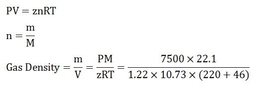
  • Calculate density of gas from the equation below;

gas density

Gas Density = 18.6 lb/cu-ft

  • Calculate gas specific gravity from the equation below;

SG = Gas Density ÷ Air Density

SG = 18.6 ÷ 28.96

SG = 0.64

Summary:

The answers for this answer are listed below;

Gas Density = 18.6 lb/cu-ft

SG = 0.64

We wish that this example will help you understand to determine z-factor and use it to calculate any related information.

References

Abhijit Y. Dandekar, 2013. Petroleum Reservoir Rock and Fluid Properties, Second Edition. 2 Edition. CRC Press.

L.P. Dake, 1983. Fundamentals of Reservoir Engineering, Volume 8 (Developments in Petroleum Science). New impression Edition. Elsevier Science.

Tarek Ahmed PhD PE, 2011. Advanced Reservoir Management and Engineering, Second Edition. 2 Edition. Gulf Professional Publishing.

Heavy Lifting ‘Mariner A’ Platform Topside Installation – Please Watch The Amazing Video

$
0
0

Norwegian energy company Statoil has completed the installation of the 38,000-tonne topside of its Mariner A production, drilling and quarters (PDQ) platform in the UK sector of the North Sea.

The topside consists of eight modules, including two that weigh more than 10,000 tonnes each, based on top of a steel jacket. On August 2, the final piece of the puzzle was lifted into place using the heavy lift vessel Saipem 7000. With the installation of the Mariner A topside complete, the platform is now connected to the Safe Boreas accommodation floatel.  The flare, a crane and some stair towers have also been installed offshore on Mariner A.

Mariner Field

Located some 250 kilometers Scotland’s north-east coast, the Mariner field will contribute more than 250 million barrels of heavy oil reserves with an average production of around 55,000 barrels per day over a period of 30 years.

Mariner A will be connected to the floating storage unit (FSU), Mariner B, where tankers will load oil produced at the field for transport to global markets.

Production is expected to commence in 2018. Drilling has already started at the field using a jack-up rig, which will assist Mariner A for the first four years.

Reference – https://www.statoil.com/
www.gcaptain.com/watch-38000-tonne-mariner-a-topside-installed-off-scotland/

What are Drilling Jars?

$
0
0

Most modern drilling jars are hydraulic. They are also usually double acting, meaning they can deliver an extra-heavy impact should the bottom hole assembly become stuck. They are intended to work as an integral part of the drill string, and can withstand high pressures and temperatures over a long period of time, making them suitable for long-term use.

With almost the same length and diameter specifications as standard drill collars, and with a similar connection strength and slip setting area, they may be used as a component of a stand of drill collars without difficulty.

Usually, jars will be used alongside accelerators, which are run above the jar and work automatically. They serve to amplify the impact force of the jar, and can even double it in some cases. They commonly use the compression of silicon to give added stored energy and optimize jar impact and free-travel distance in both directions. They also have the added benefit of dampening the dynamic load in the drillpipe, since they transmit shock waves poorly, thus helping reduce damage to both string and surface equipment.

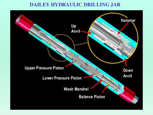
Drilling Jars Diagram (Slideshare, 2017)

Drilling Jars Diagram (Slideshare, 2017)

When normal drilling procedures are followed, the jarring mechanism will be automatically disengaged, and drilling string torque will be transmitted to the lower assembly using a separate compensated drive system. Sufficient drive lubrication is usually provided by high-temperature lubricants in most downhole conditions. Within the jar’s hydraulics are powerful seals that can withstand up to 20,000 psi up to 500°F. There are numerous back-up seals used to guard against premature failure of these drive lubrication seals and rig pump hydraulic seals.

If the amount of surface push or pull is adjusted, then there is no need of any torque or external adjustments. This allows the operator to deliver a capacity blow anywhere from very small to maximum capacity in either direction, and also to control the number of blows struck in a certain time period. The string doesn’t need to be manipulated in any other way to operate the jar, and it will be automatically reset for following blows in either direction.

Modern jars may be run in tension or compression, but it is important to note that they can’t be run at or within 15% of the natural weight. Jars also shouldn’t be run as crossovers between collars and heavy weight drill pipe, nor between drill collars of differing ODs. This is because these transition points are the places where the most extreme stress will occur, and this can increase the chances of mechanical failure. One should therefore run the same size of collar or heavy weight drill pip directly above and below the jar. Jars should not be run below key seat wipers, reamers, or other tools with a larger OD than the jar; this will have a negative effect on the jarring function.

Jars are usually in tension when the bit hits the bottom. They need to be triggered down with a light load, to minimize the risk of damage to the bit. It is recommended that one starts by rotating and slacking off weight so that the jar is only slightly in compression. When the jar has fallen through, one may then slack off to the final drilling weight. The jar will cock each time the string is lifted off the bottom, meaning this process needs to be repeated for each connection.

It is necessary to keep jars in tension when running, to prevent them from being accidentally triggered:

  • The jar can be cocked if there is too much “yo-yoing”
  • Jars should be slowly run through dog legs and tight spots
  • Any component that can restrict the ID of the pipe, whether they be float valves, survey tools, or anything else, can cause collars to float should the pipe be lowered too quickly. This can cause premature cocking

Should the jar cock accidentally, the drill pipe must be suspended in the elevator to allow the jar to trip open from the weight of the collars suspended below it, before it can be run into the hole.

There is no need to pre-set or adjust the jar before running prior to jarring. This is because jars are controlled using axial motion from the surface. To do this, from the neutral position, pull up to the desired load. After a few seconds, the jar will jar up. To jar down, do the same, but slack off to the required load. After impact, the jar should be returned to neutral. It is then immediately ready to jar again in either direction. The strength of impact will depend on how hard you pull. The jar bay be hit in any required sequence. Waiting time between setting the brake and the jarring action can range from ten to sixty seconds, and is independent of changes in downhole temperature, hydrostatic pressure, or how many times the jar is actuated. There is no need to warm up a jar, and no cooling off period. Jars are not affected by drilling torque, and the magnitude and time delay of the jarring action is similarly unaffected by how much torque is applied.

There is no need to slack off (or, if jarring down, pull) a precise amount of weight, or to control the travel of the jar, in order to re-cock it. The right travel will happen automatically so long as sufficient weight is slacked off or pulled up to allow the necessary travel at the tool.

Should the drill string get stuck on the bottom while drilling, or if twist offs happen, then a jar may deliver its releasing effort in an upwards motion. If the pipe becomes stuck off-bottom in key seats, or if it is stuck because of other reasons, it can be released by jarring downwards. The upward reaming methods can then be used in order to recover the whole drill string.

Should differential sticking be encountered, it may be necessary to move the stuck pipe to regain rotation and circulation, so that, for instance, jars can move up and down as normal. A jar actuation won’t disturb the directional orientation of the drillstring, so they are useful neutral tools for downhole motor directional drilling and directional jetting.

Jars are also of use in fishing and cutting jobs, as well as for drilling and production tools, cementing, coring operations, and multiple downhole operations.

Example of drilling jars in the market

References

Inglis, T.A. (2010) Directional drilling. Dordrecht: Springer-Verlag New York.

Mitchell, R.F., Miska, S.Z. and Aadnoy, B.S. (2012) Fundamentals of drilling engineering. Richardson, TX: Society of Petroleum Engineers.

Nov.com. (2018). National Oilwell Varco. [online] Available at: https://www.nov.com/Segments/Wellbore_Technologies/Downhole/Drilling_Tools/Reamers_and_Wipers/DL_Reamer.aspx [Accessed 17 Jan. 2018].

Schlumberger Limited (2017) Schlumberger Drilling Services. Available at: http://www.slb.com/services/drilling.aspx (Accessed: 25 February 2017).

Short, J.J.A. (1993) Introduction to directional and horizontal drilling. Tulsa, OK: PennWell Books.

Technical, T., Astier, B., Baron, G., Boe, J.-C., Peuvedic, J.L.P. and French Oil & Gas Industry Association (1990) Directional drilling and deviation control technology. Paris: Editions

Learn about Maximum Surface Pressure in Well Control (MASP, MISICP and MAASP)

$
0
0

There are several terms/acronyms about maximum surface pressure in well control such as MASP, MISICP and MAASP. These terms sometimes confuses a lot of people hence this article will explain each term and demonstrate how to use it.

26-MASP-MISICP-MAASP-cover

Leak Off Test (LOT)

The first factor you need to understand is Leak of test pressure (LOT). LOT is the surface pressure that breaks down formation at a casing shoe for each section of the well.

Leak off test pressure formula is listed below;

Leak off test pressure, psi = Surface pressure to break formation, psi + Hydrostatic pressure, psi

Typically, leak off test pressure is describe in equivalent mud density term therefore the formulas will be like this

Leak off test pressure, ppg = (Surface pressure to break formation, psi ÷ 0.052 ÷ shoe TVD, ft) + Mud weight, ppg

Maximum Allowable Surface Pressure (MASP)

Maximum Allowable Surface Pressure (MASP) is based on surface equipment rating and most of the time, the MASP is determined by a percentage of the casing burst pressure. Generally, 80% is used for derating from the original casing burst pressure however it can be less than 80% if the well is very old and the casing is in very bad shape.

MASP, psi = percentage of casing burst x casing burst pressure, psi

Maximum Initial Shut-In Casing Pressure (MISICP)

Maximum Initial Shut-In Casing Pressure (MISICP) is the maximum casing pressure before fracturing the casing shoe when the well is shut due to well control. MISICP formula is listed below;

 MISICP, psi = (Leak Off Test pressure, ppg – current mud weight, ppg) x 0.052 x Casing shoe TVD, ft

Maximum Allowable Annular Surface Pressure (MAASP)

Maximum Allowable Annular Surface Pressure (MAASP) is the maximum annular pressure which will cause formation break down. MAASP can be in a static condition and a dynamic condition (circulating).

At the static condition, MAASP will be same as MISICP and the equation is listed below;

MAASP, psi = (Leak Off Test pressure, ppg – current mud weight, ppg) x 0.052 x Casing shoe TVD, ft

At the dynamic condition, due to friction pressure in the annulus while circulating, it is very difficult to calculate an accurate MAASP therefore it is not recommended to determine the dynamic MAASP while circulating the kick out of the well. Furthermore, you should NOT use MASSP at the static condition while circulating. For example, you determine the static MASSP of 1000 psi and while circulating, casing pressure can go more than 1000 psi. If you try to lower the casing pressure down by misleading the interpretation of this value, the additional kick will go into the well and finally it will make the well control situation even worse.

Example: 9-5/8” casing was set at 8,500MD/8,000’TVD.

9-5/8” casing : L-40, 43.5 lb/ft, burst pressure = 6,330 psi, collapse pressure =3,810 psi

Leak off test at 9-5/8” casing shoe = 15.0 ppg equivalent mud weight

Current hole depth is 12,000’MD/10,000’TVD and current mud weight is 10.0 ppg

20% de-rate burst pressure

Figure 1 - Well Schematic

Figure 1 – Well Schematic

Determine: MASP, MASSP, MISICP with current mud weight. What will happen if the current mud weight is 12.0 ppg?

Maximum Allowable Surface Pressure (MASP) = 0.8 x 6330 psi = 5064 psi

Maximum Initial Shut-In Casing Pressure (MISICP) = (15 – 10) x 0.052 x 8,000 = 2,080 psi

Maximum Allowable Annular Surface Pressure (MAASP) at the static condition is equal to MISICP.

Maximum Allowable Annular Surface Pressure (MAASP) = (15 – 10) x 0.052 x 8,000 = 2,080 psi

At dynamic condition, you need to determine the frictional pressure to get an accurate dynamic MAASP.

For this case, if the well is shut in due to well control, the weakest point is at the shoe because it will be fractured before the surface equipment fails.

If the mud weight increases to 12.0 ppg, MISICP and static MAASP will reduce.

MISICP = static MAASP = (15 – 12) x 0.052 x 8,000 = 1,248 psi.

Conclusions:

  • MAASP in a static condition is the same as MISICP.
  • MASP depends on how the surface equipment looks like. It may be derated due to corrosion, age, etc and it can be the weakest point of the well.
  • The higher the mud weight is, the lower MAASP and MISICP are.

Reference books: Well Control Books


Fatality Drilling Rig Accident, Oilfield Worker was Knocked 6 feet to the floor

$
0
0

This is the oilfield incident resulting in our friend working on the rig got killed. It is very important that we need to heavily focus on the safety. Every year, people get injured due to several causes while working in the oilfield. For this case, there are several contributing factors the high pressure, line of fire, equipment inspection, etc. We want you to work safely for yourself and your family.

 land-rig

A high-pressure gate valve that came off a leaky standpipe on a Cyclone rig north of Parachute early in the evening of Oct. 21 struck and killed Shane Hill, 34, of Grand Junction and blew his body 6 feet away from the valve, a state report says.
The rig was being operated for WPX Energy.

The accident report filed with the Colorado Oil and Gas Conservation Commission said that the rig’s day crew had tightened a leaking standpipe and fitted it with a new gasket. The day driller informed the night crew of the repair, but when the evening crew took over, the pipe began to leak again.
Operators decided to shut down and repair the leaking gasket. The crew began by attempting to dislodge a manifold to perform the repair. After several attempts to dislodge the manifold, the crew decided that removing a 2-inch fill-up flex line was necessary. Workers did that and replaced the gasket.
The manifold was put back in position and tightened. The rig manager gave the word for the driller to turn the pumps on and pressurize the system to allow the rig to resume drilling.

“Once the system was pressurized to 2,700 psi, the 2-inch high-pressure gate valve parted from the 2-inch high-pressure nipple on the standpipe, striking [Hill],” the report said.
Hill was struck on the back of the head, according to Garfield County deputy coroner Thomas Walton.

After the drilling fluid cleared, the crew reported finding Hill approximately 6 feet away from the valve. Efforts by crew members and emergency medical workers to revive him were unsuccessful, the report said.

Source: Post Independent


The post Fatality Drilling Rig Accident, Oilfield Worker was Knocked 6 feet to the floor appeared first on Drilling Formulas and Drilling Calculations.

Why Do We Keep Cement Samples in Oil Well Operations?

$
0
0

We Keep Cement Samples Because of The Following Reasons

Cement samples are kept after pumping cement in oil well operations for several important reasons. The two images below shoes cement samples, one collected while cement is in liquid phase and another one is when cement is set for awhile.

Cement Sample in Liquid Phase

Cement Sample After Set

Cement Sample After Set

Quality control

Cement samples allow operators to assess the quality of the cement used in well construction. The samples can be analyzed for various properties, such as compressive strength, setting time, and density, to ensure that the cement meets the required specifications and standards. This is crucial for maintaining the integrity and safety of the well.

Verification

Cement samples serve as a reference to verify that the cement placed downhole matches the intended composition and properties. By comparing the downhole cement with the sample, operators can confirm that the correct cement was used and that it has set properly.

Troubleshooting

In case of any issues with the cementing process, such as poor bonding or incomplete setting, having samples allows engineers to investigate the problem and make necessary adjustments for future operations.

Regulatory compliance

In the oil and gas industry, there are often regulatory requirements related to well construction and cementing. Keeping samples can provide evidence of compliance with these regulations and may be required for audits or reporting.

Research and development

Cement samples can also be valuable for research and development purposes. They can be used to develop and test new cement formulations, additives, and techniques to improve wellbore stability and integrity.

Litigation and liability

In the event of disputes, accidents, or liability claims related to well construction, having cement samples can serve as valuable evidence to support claims or defend against them.

Additionally, cement samples are also required by law in some jurisdictions. For instance, such as the United States, the Environmental Protection Agency (EPA) mandates that oil and gas companies retain cement samples for a stipulated period of three years.

These samples find diverse applications:

  1. Well Abandonment: When a well is abandoned, cement samples undergo testing to confirm the continued integrity of the cement sheath. This evaluation ensures that the cement effectively prevents the migration of hydrocarbons or other substances to the surface.
  2. Well Reuse: In cases where a well is earmarked for reuse, possibly for activities like carbon capture and storage, cement samples are subjected to scrutiny. This examination guarantees that the cement is compatible with the new fluids slated for injection into the wellbore.
  3. Troubleshooting: For wells encountering issues like corrosion or erosion, cement samples become instrumental. They are tested to ascertain whether the cement composition is contributing to the observed problems.

Summary

Retaining cement samples in oil well operations is a standard practice that is essential for ensuring the quality, performance, and compliance of the cement used in the well construction process. This is critical for maintaining the safety and productivity of oil and gas wells.

In addition to practical applications, such as quality control and troubleshooting, cement samples are also indispensable for compliance with legal requirements. By keeping cement samples, oil well operators can demonstrate that they are operating within the regulatory framework set by authorities like the EPA.

In short, cement samples play a vital role in ensuring the safety and integrity of oil and gas wells.

<p>The post Why Do We Keep Cement Samples in Oil Well Operations? first appeared on Drilling Formulas and Drilling Calculations.</p>

Jack Up Rig for Oil Well Drilling: Let’s Get More Understanding about This Drilling Rig for Offshore Drilling

$
0
0

A jack up rig is a mobile offshore drilling platform commonly used for oil and gas exploration and production in shallow waters. It’s a versatile and efficient platform that offers several advantages over other types of drilling rigs.

Component of a Jack-Up Rig:

Barge or Hull: The primary structure of the rig contains machinery space, generators, mud pits, mud pumps, other drilling equipment, and crew living quarters.

Legs: Typically, three or four retractable legs that can be lowered to the seabed, enabling the rig to be elevated above the mean seal level.

Jacking System: Utilizing hydraulic jacks or electric motors, this system raises and lowers the rig’s legs as needed.

Drilling Equipment: This consists of the derrick, drawworks, mud pumps, and other essential tools for drilling oil and gas wells.

Cantilever: An extended platform over the water that facilitates drilling over the production platform or drilling in the open water location for exploration wells.

Advantages of a jack up rig are as follows;

Mobile: Easily transportable from one location to another.

Stable: Offers a reliable platform for drilling operations in shallow waters.

Self-Contained: Operates independently for extended periods without shore support.

Cost-Effective: Relative cost-efficiency compared to other offshore drilling rigs.

Disadvantages of a jack up rig are as follows;

Limited Water Depth: Operational up to approximately 400 feet of water depth.

Weather-Sensitive: Susceptible to the influence of strong winds and waves.

Environmental Impact:  The jacking process may disturb the seabed and marine life.

Exploring Jack-Up Rigs: Additional Facts:

The first jack-up rig was built in 1954! It was a significant milestone in offshore drilling, marking the beginning of a new era of mobility and efficiency for shallow-water operations.

There are a couple of different contenders for the exact title of the “first”:

  • DeLong Rig No. 1: Built by J.H. DeLong in 1954, this rig is often credited as the first true jack-up, with three retractable legs and a jacking system that allowed it to operate in water depths up to 15 feet.
  • McDermott No. 1: Developed by a joint venture between DeLong and McDermott in 1954, this rig also laid claim to the title of “first,” showcasing a similar jacking system and leg design as DeLong Rig No. 1.

The world’s largest jack-up rig is Maersk Invincible: This rig, built by DSME in South Korea and delivered to Maersk Drilling in 2016, has legs measuring 206.8 meters (678 feet) long, making it the rig with the longest legs in the world. It’s designed for year-round operation in the North Sea, in water depths up to 150 meters.

Maersk Invincible

Maersk Invincible

Beyond oil and gas, jack-up rigs find utility in wind farm construction and offshore platform maintenance.

Conclusion:

Jack-up rigs emerge as curtail offshore rigs in the realm of oil and gas exploration within shallow water area. Their mobility, stability, self-sufficiency, and cost-effectiveness underscore their value, despite limitations related to water depth and susceptibility to weather conditions. In addition to their primary role in hydrocarbon exploration and production, these versatile rigs continue to contribute to diverse applications, shaping the landscape of offshore engineering.

<p>The post Jack Up Rig for Oil Well Drilling: Let’s Get More Understanding about This Drilling Rig for Offshore Drilling first appeared on Drilling Formulas and Drilling Calculations.</p>

What Factors To Be Considered When to Change Annular Preventer Element

$
0
0

An annular rubber element stands as a pivotal component within an annular blowout preventer (BOP), playing a crucial role in safeguarding oil well drilling operations by preventing the uncontrolled release of formation fluids, such as oil, gas, or water, from the wellbore.

When to Change Annular Preventer Element

When to Change Annular Preventer Element

Crafted from a high-performance elastomer compound, these elements are engineered to withstand the demanding conditions of the downhole environment. Subjected to high pressures, extreme temperatures, and exposure to corrosive fluids, they are strategically placed around the wellbore within the BOP body to forge a seal between the drill pipe or casing and the wellbore wall.

Upon activation of the BOP, the element undergoes compression, forming a tight seal that effectively halts the flow of fluids up the wellbore. Available in various sizes and configurations, annular rubber elements cater to diverse wellbore conditions and applications.

Here are some primary functions of annular rubber elements:

  1. Primary Pressure Barrier: The element serves as the primary barrier against the upward flow of formation fluids throughout drilling, completion, and production phases.
  2. Accommodation of Different Pipe Sizes: Designed to adapt to a range of pipe diameters, ensuring a secure seal irrespective of the size of the drill pipe or casing utilized.
  3. Resistance to Wear and Tear: Manufactured from robust materials capable of withstanding the abrasive downhole conditions.
  4. Maintenance of Flexibility: Flexibility is paramount for the element to conform to the irregularities of the wellbore wall and pipe while maintaining a tight seal.

The decision to replace an annular rubber element in an annular BOP is critical for wellbore safety and should be approached on a case-by-case basis, taking into account various factors. Here are key indicators that replacement might be necessary:

This is an example of worn out annular rubber element.

This is an example of worn out annular rubber element.

Visual Inspection:

  • Visible Damage: Any cuts, tears, abrasions, nicks, or physical damage compromise the sealing ability and warrant replacement.
  • Excessive Wear: Significant or uneven wear suggests the end of the element’s useful life.
  • Swelling or Softening: Signs of exposure to incompatible fluids or excessive heat indicate weakening and necessitate replacement.

Performance Issues:

  • Leaks: Even minor leaks around the element necessitate investigation and potential replacement.
  • Increased Activation Pressure: Elevated pressure requirements could signify wear or damage, reducing sealing effectiveness and calling for replacement.

Preventative Maintenance:

  • Manufacturer Recommendations: Adhering to recommended replacement intervals ensures optimal performance and safety.
  • Pre-operational Inspections: Scheduled inspections before each operation enable early detection of potential issues.
  • Records and History: Detailed records of element usage aid in predicting replacement needs.

Additional Factors:

  • Wellbore Conditions: Harsh environments accelerate wear, necessitating more frequent replacements.
  • Drilling Operations: Operations involving abrasive materials or frequent pressure cycling influence replacement decisions.

Replacing an annular rubber element is a critical safety measure. Consultation with experienced personnel, qualified inspectors, and adherence to industry regulations is imperative for informed replacement decisions. Never delay replacement if there are suspicions regarding the integrity or performance of the element.

References 

Cormack, D. (2007). An introduction to well control calculations for drilling operations. 1st ed. Texas: Springer.

Crumpton, H. (2010). Well Control for Completions and Interventions. 1st ed. Texas: Gulf Publishing.

Grace, R. (2003). Blowout and well control handbook [recurso electrónico]. 1st ed. Paises Bajos: Gulf Professional Pub.

Grace, R. and Cudd, B. (1994). Advanced blowout & well control. 1st ed. Houston: Gulf Publishing Company.

Watson, D., Brittenham, T. and Moore, P. (2003). Advanced well control. 1st ed. Richardson, Tex.: Society of Petroleum Engineers.

<p>The post What Factors To Be Considered When to Change Annular Preventer Element first appeared on Drilling Formulas and Drilling Calculations.</p>

Best Practices for Drilling Coal Formations in Long Tangent Wells Using Water-Based Mud

$
0
0

Drilling through coal formations, especially in long tangent wellbores, presents a unique set of challenges for the oil and gas industry therefore we need best practices for drilling coal formations. Coal seams are notorious for their potential instability, abnormal formation pressures, and propensity for swelling and sloughing when exposed to water-based drilling fluids. These challenges can lead to various drilling problems, such as stuck pipe incidents, lost circulation events, and well control situations, ultimately compromising the safety and efficiency of drilling operations.

Coal over shale shakers

Coal over shale shakers

When drilling extended reach or horizontal wells with tangent sections, the complexities associated with coal formations are further amplified. The increased wellbore exposure to these challenging formations, coupled with the difficulties in maintaining adequate hole cleaning and wellbore stability in long tangent intervals, necessitates a comprehensive approach to mitigate risks and ensure successful drilling operations.

Using water-based muds for drilling coal formations introduces additional considerations, as these fluids can interact with the reactive shale and coal layers, potentially exacerbating wellbore instability issues. Consequently, careful mud design, composition, and treatment are paramount to maintain the desired mud properties and mitigate formation-related challenges.

The best practices for drilling coal formations in long tangent wells using water-based mud systems are listed below;

Mud Weight and Density Control:

Coal formations are often associated with abnormal formation pressures, either overpressured or underpressured. Maintaining the correct mud weight and density is crucial to prevent kicks (influx of formation fluids) or lost circulation events. Regular formation pressure integrity tests (FIT) and careful pore pressure/fracture gradient analysis should be performed to optimize the mud weight.

Mud Composition and Inhibition:

Coal formations are prone to swelling and sloughing when exposed to water-based muds. The mud should be properly inhibited with potassium chloride (KCl) or other shale inhibitors to minimize wellbore instability. Maintaining a slightly alkaline pH (8.5-9.5) can also help mitigate shale/coal instability.

Hydraulics and Hole Cleaning:

Maintaining effective hole cleaning is of paramount importance in long tangent sections to prevent the accumulation of formation cuttings, which can lead to potential wellbore instability issues and compromised drilling performance.

To enhance cuttings removal and mitigate associated risks, operators should consider employing high-viscosity pills or performing wiper trips, which involve circulating a viscous fluid or specialized pills to displace and lift cuttings from the wellbore effectively.

Drilling Fluids Monitoring and Treatment:

Coal formations can release methane, carbon dioxide, and other gases, which can affect the mud properties and potentially cause kick situations. Regular monitoring of gas levels, mud weight, and rheological properties is essential. Appropriate solids control equipment and treatments (e.g., degassers, defoamers) may be necessary to maintain the desired mud properties.

Wellbore Stability and Casing Design:

Coal formations are often associated with unstable wellbore conditions due to their swelling and sloughing tendencies. Proper casing design, including casing setting depths, mud weights, and potential use of expandable casing or liners, should be considered to maintain wellbore stability.

Bit Selection and Drilling Parameters:

Coal formations can be abrasive and challenging to drill, leading to increased bit wear and potential stuck pipe situations. Selecting the appropriate bit type (e.g., PDC, impreg, or roller cone) and optimizing drilling parameters (WOB, RPM, ROP) is crucial for efficient and safe drilling operations.

Real-time monitoring while drilling:

Utilizing formation evaluation tools while drilling is crucial to identify coal seams and other potential hazards, allowing for timely adjustments to mud properties and drilling parameters to mitigate risks proactively.

Continuous monitoring of key drilling parameters, such as torque and drag, is essential to detect early signs of wellbore instability. Prompt corrective actions, such as modifying mud properties, adjusting drilling parameters, or implementing contingency plans, should be taken to prevent further deterioration of wellbore conditions and potential stuck pipe incidents.

Team collaboration:

Successful drilling of coal formations in long tangent wells necessitates close collaboration among the drilling team, mud engineers, and geologists. The drilling team executes operations while working closely with mud engineers to design inhibitive muds that control coal swelling and maintain proper rheology. Geologists provide critical insights into formation characteristics, hazards, and pore pressures to guide drilling parameters and casing design. This multidisciplinary teamwork enables informed decision-making, proactive adjustments, and timely implementation of contingency plans for safe and efficient operations.

What is your experience about drilling through coal? 

Please feel free to share in the comment section below.

<p>The post Best Practices for Drilling Coal Formations in Long Tangent Wells Using Water-Based Mud first appeared on Drilling Formulas and Drilling Calculations.</p>

What is a Cathead in a Drawworks and Its Function in Drilling Operation?

$
0
0

A cathead is a vital piece of equipment in the complex operations of a drilling rig, functioning in many ways like a powerful winch. This device, a clutched spool connected to the drawworks’ power system, is essential for managing tension on chains, cables, or softline ropes, significantly contributing to the efficiency and safety of rig operations.

The cathead’s design is straightforward but effective. It consists of a concave, grooved pulley mounted on a shaft that spins, resembling a simple yet robust spool. This simplicity in design allows it to perform a variety of tasks, making it an indispensable tool on a drilling rig.

Cathead Image

Cathead Image

At its core, the primary function of a cathead is to assist with lifting and pulling tasks around the rig. When engaged, the cathead controls the tension on ropes or chains, making it essential for several critical applications. One of the most common uses of the cathead is for lifting equipment. By attaching ropes or slings to the cathead, crew members can lift and move various tools and equipment around the rig with ease. This not only enhances operational efficiency but also significantly improves safety, as heavy and cumbersome items can be moved more precisely and securely.

In addition to lifting, the cathead is crucial for pulling lines. During operations such as the removal of drill pipe sections, the cathead is used to tension guide lines or pull lines. This capability ensures that these processes are carried out smoothly and efficiently, reducing the risk of delays or accidents. The controlled tension provided by the cathead is particularly important in maintaining the stability and alignment of equipment, which is essential for the successful completion of drilling operations.

The cathead also plays a significant role in catline operations. A catline refers to a line specifically powered by the cathead, typically used for lighter lifting tasks or to assist in maneuvering equipment. This adds another layer of utility to the cathead, making it an essential tool for a wide range of activities on the rig. The ability to perform lighter lifting tasks without the need for additional equipment further enhances the efficiency and flexibility of drilling operations.

Image of a Cathead

Image of a Cathead

Drawworks on a drilling rig typically feature one or two catheads, mounted on either side of the main drum. This placement allows for balanced and efficient operation, ensuring that the cathead can provide the necessary support for the varied tasks it is required to perform. The strategic positioning of the catheads enhances their functionality, allowing them to be easily accessed and utilized during different stages of the drilling process.

Overall, the cathead significantly enhances the functionality of the drawworks by providing additional winching and pulling capabilities. Its role in lifting and tensioning lines improves the efficiency of operations on the drilling rig. Whether it’s lifting heavy equipment, pulling lines during critical operations, or assisting with lighter tasks through catline operations, the cathead proves to be a versatile and invaluable tool in the demanding environment of a drilling rig.

In conclusion, the cathead is a specialized and essential component of drilling rig operations. Its ability to control tension on ropes and chains, lift and move equipment, and assist with various pulling tasks makes it a critical asset in maintaining the efficiency and safety of drilling activities. The straightforward yet effective design of the cathead, combined with its strategic placement on the drawworks, ensures that it can perform its functions reliably and effectively. As drilling technology continues to evolve, the importance of the cathead in facilitating safe and efficient operations remains undiminished, highlighting its enduring value in the oil and gas industry.

<p>The post What is a Cathead in a Drawworks and Its Function in Drilling Operation? first appeared on Drilling Formulas and Drilling Calculations.</p>

Example of Real Gas Calculation

$
0
0

This example will demonstrate how to calculate the compressibility of real gas in order to determine gas density and specific gravity at a specific condition.

Calculate the following based on the given condition:

1) Density of this gas under the reservoir conditions of 7,500psia and 220ºF,

2) Specific gravity of the gas.

Gas component is shown in Table 1

Table 1 - Gas Component

Table 1 – Gas Component

Average density of air = 28.96 lb/cu-ft

Solution

  • Determine critical pressure and temperature of gas mixtures using Kay’s rule
Table 2 - Critical Pressure and Temperature

Table 2 – Critical Pressure and Temperature

Note: critical pressure and temperature can be found from this link – http://www.drillingformulas.com/determine-compressibility-of-gases/

Pc’ = Σyipci = 660.5 psia

Tc’ = ΣyiTci = -46.2 F = -46.2 +460 F = 413.8 R

Table 3 - Pc' and Tr' by Kay's Rule

Table 3 – Pc’ and Tr’ by Kay’s Rule

  • Calculate Tr and Pr

Tr = T ÷Tc

Tr = (220+460) ÷ (-46.2+460)

Tr = 1.64

Note: temperature must be in Rankin.

Rankin = Fahrenheit + 460

For the critical temperature calculation, it can be converted the critical temperature from F to R before calculating Tc’. This will still give the same result. 

Pr = P ÷ Pc

Pr = 7500 ÷ 660.5 = 11.4

  • Read the compressibility factor (z) from the chart.

z = 1.22

Figure 1-z-factor from the Standing and Katz Chart

Figure 1-z-factor from the Standing and Katz Chart

  • Calculate average molar mass

Average Molar Mass = Σyi×Mi = 22.1 lb

Table 4 - Average Molar Mass of Gas

Table 4 – Average Molar Mass of Gas

  • Calculate density of gas from the equation below;

gas density

Gas Density = 18.6 lb/cu-ft

  • Calculate gas specific gravity from the equation below;

SG = Gas Density ÷ Air Density

SG = 18.6 ÷ 28.96

SG = 0.64

Summary:

The answers for this answer are listed below;

Gas Density = 18.6 lb/cu-ft

SG = 0.64

We wish that this example will help you understand to determine z-factor and use it to calculate any related information.

References

Abhijit Y. Dandekar, 2013. Petroleum Reservoir Rock and Fluid Properties, Second Edition. 2 Edition. CRC Press.

L.P. Dake, 1983. Fundamentals of Reservoir Engineering, Volume 8 (Developments in Petroleum Science). New impression Edition. Elsevier Science.

Tarek Ahmed PhD PE, 2011. Advanced Reservoir Management and Engineering, Second Edition. 2 Edition. Gulf Professional Publishing.

<p>The post Example of Real Gas Calculation first appeared on Drilling Formulas and Drilling Calculations.</p>


What is a Ton-Mile in Drilling Operations?

$
0
0

What is a Ton-Mile?

A ton-mile is a measurement that quantifies the cumulative load exerted on a drilling line. This is done by multiplying the load lifted (measured in tons) by the distance it is lifted or lowered (measured in miles). Essentially, it represents the total work done by the drilling line during drilling operations.

To break it down:

  • Load: This is the weight of the drill string, which includes the drill pipe, drill collar, and drill bit. These components together can be extremely heavy, with the weight typically measured in tons.
  • Distance: This refers to the vertical distance the drill string is moved, either up or down, during drilling operations. This distance is measured in miles.

For example, if a drill string weighing 10 tons is lifted 2 miles, the ton-mile value would be 20 ton-miles.

The Importance of Ton-Miles in Drilling Operations

Understanding and monitoring ton-miles is critical for several reasons:

  1. Wear and Tear on Drilling Lines: Drilling lines are subjected to immense stress during operations. Each time the drill string is lifted or lowered, the drilling line bears the load. Over time, this repeated stress causes wear and tear on the line. By calculating the ton-miles, operators can quantify the cumulative stress experienced by the drilling line. A higher ton-mile reading indicates that the line has been subjected to more stress, which may mean it is approaching the end of its service life.
  2. Maintenance and Safety: Safety is paramount in drilling operations, and one of the key factors in maintaining safety is ensuring that equipment is in good working order. Drilling lines that have experienced a high number of ton-miles are more likely to fail, which can lead to catastrophic consequences. By monitoring ton-miles, operators can establish predetermined limits at which the drilling line should be inspected or replaced. This proactive approach to maintenance helps prevent unexpected failures, ensuring the safety of the crew and the integrity of the operation.
  3. Operational Efficiency: Downtime in drilling operations can be extremely costly. By keeping track of ton-miles, operators can predict when maintenance or replacement will be needed, allowing them to schedule it during planned downtimes rather than in response to unexpected failures. This predictive maintenance approach not only reduces downtime but also improves overall efficiency by ensuring that the drilling line is always in optimal condition.

Calculating Ton-Miles in Practice

To calculate the ton-miles in a drilling operation, you need two key pieces of information: the weight of the drill string (in tons) and the vertical distance it is moved (in miles). The formula is simple:

Ton-Miles = Load (tons) x Distance (miles)

For example, if a drill string weighs 15 tons and is lifted 1.5 miles, the ton-mile calculation would be:

Ton-Miles = 15 tons x 1.5 miles = 22.5 ton-miles

This calculation would be repeated for every lift or lowering operation, with the cumulative ton-miles providing a total measure of the stress on the drilling line over time.

Managing Ton-Mile Data

In modern drilling operations, ton-mile data is often tracked using advanced monitoring systems. These systems can automatically calculate and record ton-miles for each operation, providing real-time data to operators. This data is then used to inform maintenance schedules and ensure that equipment is inspected or replaced before it reaches a critical wear point.

Moreover, operators may use ton-mile data to optimize drilling operations. For example, by analyzing ton-mile trends, they can identify patterns that indicate inefficiencies or potential issues with equipment. Addressing these issues proactively can lead to significant cost savings and improve the overall productivity of the drilling operation.

Conclusion

The concept of ton-miles is a fundamental aspect of drilling operations, serving as a critical measure of the wear and tear on drilling lines. By understanding and monitoring ton-miles, operators can enhance the safety, efficiency, and longevity of their drilling equipment. Whether through routine inspections or advanced monitoring systems, keeping track of ton-miles ensures that drilling lines are maintained in optimal condition, minimizing the risk of failure and maximizing operational success. In the high-stakes world of drilling, this seemingly simple measurement plays a vital role in ensuring that operations run smoothly and safely.

<p>The post What is a Ton-Mile in Drilling Operations? first appeared on Drilling Formulas and Drilling Calculations.</p>

Applying Makeup Torque Using a Rig Tong: Explanation and Calculation Example

$
0
0

In oil and gas drilling operations, torque is a crucial factor in ensuring that drill pipes, casings, and other tubular components are securely connected. Makeup torque is the force applied to tighten the connection between two pipes, ensuring a proper seal and structural integrity during drilling. Understanding how to calculate and apply makeup torque is essential for maintaining safe and efficient operations, and rig tongs play a vital role in this process.

This article will explain how makeup torque is applied using a rig tong and provide a calculation example to illustrate the process.

What is Torque?

Torque is the measure of the rotational force applied to an object. In the context of oil and gas drilling, it refers to the twisting force used to connect two sections of pipe. Proper makeup torque ensures that the pipes are joined tightly, preventing leakage and maintaining the strength of the connection under high-pressure and high-stress conditions.

The formula for torque (T) is expressed as:

T=F×L

Where:

T = Torque (measured in foot-pounds or Newton-meters)

F = Force applied (measured in pounds or Newtons)

L = Length of the lever arm (measured in feet or meters)

Applying Makeup Torque with Rig Tongs

Rig tongs are large, heavy-duty tools used to apply torque to pipes during drilling operations. They function similarly to a wrench but are designed to handle the extreme forces required for oil and gas applications. The amount of torque generated depends on the force applied to the tong’s arm and the arm’s length.

The arm length (L) refers to the distance from the point where the pulling force is applied to the center of the connection being tightened. The line pull (F) is the force exerted at the end of the tong arm, and it creates the necessary torque to screw the pipes together. To achieve the desired torque, the pulling force must be applied at a 90° angle to the tong arm as shown in the diagram below.

Calculation Example

Let’s go through a calculation example to demonstrate how to determine the pulling force needed for a specific makeup torque.

Given Information:

  • Pipe: 7 3/4” Drill Collar (DC) with a 6 5/8” regular connection
  • Recommended makeup torque: 58,500 ft-lbs (79,315 Nm)
  • Tong type: HT 65
  • Tong arm length: 4.25 ft (1.29 m)

The formula to calculate the required force is:

F=T÷L

Substituting the given values:

F (lb) = 58,500 ft-lbs ÷ 4.25 ft

F (lb) = 13,765 lbs

Therefore, a pulling force of approximately 13,765 lbs is required to achieve the recommended makeup torque using the HT 65 tong with a 4.25 ft arm length.

Key Points to Consider

  1. Proper Torque Application: Applying the correct makeup torque is essential to prevent connection failure, leakage, or damage to the pipes during drilling operations. Insufficient torque can lead to loose connections, while excessive torque can cause thread damage or even pipe breakage.
  2. Torque Equipment: The choice of rig tong is critical, as it must be capable of delivering the required torque. In our example, the HT 65 tong is appropriate for the specified torque requirements.
  3. Safety: When applying makeup torque, ensure all personnel maintain a safe distance from the rig tong and pull line to avoid injuries due to sudden movements or slippage.

Conclusion

Understanding how to calculate and apply makeup torque is a fundamental aspect of drilling operations in the oil and gas industry. By using the formula F=T÷L, operators can determine the exact pulling force required to achieve the desired torque, ensuring a secure and reliable connection between pipes. Proper application of torque using rig tongs like the HT 65 ensures the safety, efficiency, and longevity of drilling equipment, contributing to the overall success of drilling operations.

<p>The post Applying Makeup Torque Using a Rig Tong: Explanation and Calculation Example first appeared on Drilling Formulas and Drilling Calculations.</p>

How to Calculate Weight of Casing or Conductor in lb/ft Based on Pipe OD and ID

$
0
0

In this article, we will show you how to calculate weight of casing or conductor in lb/ft based on known value of pipe OD and ID. When working in drilling operations, accurately knowing the weight of the casing or conductor pipe is essential for ensuring safety and efficiency. This weight is typically measured in pounds per foot (lb/ft). While standard specifications provide this information, there are instances when you only have access to the pipe’s outer diameter (OD) and inner diameter (ID). In such cases, you can calculate the weight using a straightforward formula.

The Formula for Calculating Pipe Weight

To calculate the weight of the casing or conductor pipe per unit length (lb/ft) based on the pipe’s outside and inside diameters, you can use the following formula:

Where:

OD = Outside diameter of the pipe (in inches)

ID = Inside diameter of the pipe (in inches)

Carbon Steel Density (lb/in³) = Density of the steel used in the pipe, typically around 0.282 to 0.291 lb/in³

This formula accounts for the pipe’s cross-sectional area and the density of the carbon steel material to estimate the pipe weight per foot. This is not suitable for drill pipe or heavy weight drill pipe which has tool joints.

Understanding the Components of the Formula

  • 9.4248: This constant converts the result into lb/ft.
  • (OD² – ID²): Represents the difference in the cross-sectional area between the outside and inside of the pipe.
  • Carbon Steel Density: Pure carbon steel generally has a density of around 7.8 g/cm³, which translates to approximately 0.284 lb/in³. However, due to variations in alloying elements, the density can range from 0.282 to 0.291 lb/in³. For practical calculations, using a density value of 0.288 to 0.291 lb/in³ provides a reliable estimate.

Example Calculation

Let’s illustrate this with an example:

  • Pipe OD = 7 inches
  • Pipe ID = 6.184 inches
  • Carbon Steel Density = 0.288 lb/in³ (for this calculation)

Applying the formula:

Pipe weight (lb/ft)=9.4248×(7²−6.184²)×0.288

The estimated pipe weight is 30 lb/ft.

Practical Use of This Calculation

This formula is invaluable when you need to quickly estimate the weight of casing or conductor pipe but don’t have detailed specifications on hand. For instance, if you’re working on-site and need to confirm transportation requirements, this calculation helps you plan efficiently. It’s also helpful when designing drilling programs or planning lifting operations, as accurate pipe weights are critical for safety. By understanding and applying this formula, you can ensure accurate weight estimations, leading to safer and more efficient drilling operations.

<p>The post How to Calculate Weight of Casing or Conductor in lb/ft Based on Pipe OD and ID first appeared on Drilling Formulas and Drilling Calculations.</p>

Viewing all 38 articles
Browse latest View live


<script src="https://jsc.adskeeper.com/r/s/rssing.com.1596347.js" async> </script>